
Method for transmitting communication data in a communication system

a communication system and communication data technology, applied in data switching networks, digital transmission, network connections, etc., can solve the problems of loss in the quality of user data to be transmitted between two communication, etc., to reduce the loss of quality during the transmission of user data between heterogeneous transmission methods

Active Publication Date: 2005-05-26
UNIFY GMBH & CO KG
View PDF17 Cites 10 Cited by
  • Summary
  • Abstract
  • Description
  • Claims
  • Application Information

AI Technical Summary

Benefits of technology

[0011] The object of the invention is to provide means through the use of which a loss in quality during a transmission of user data between heterogeneous transmission methods is reduced.
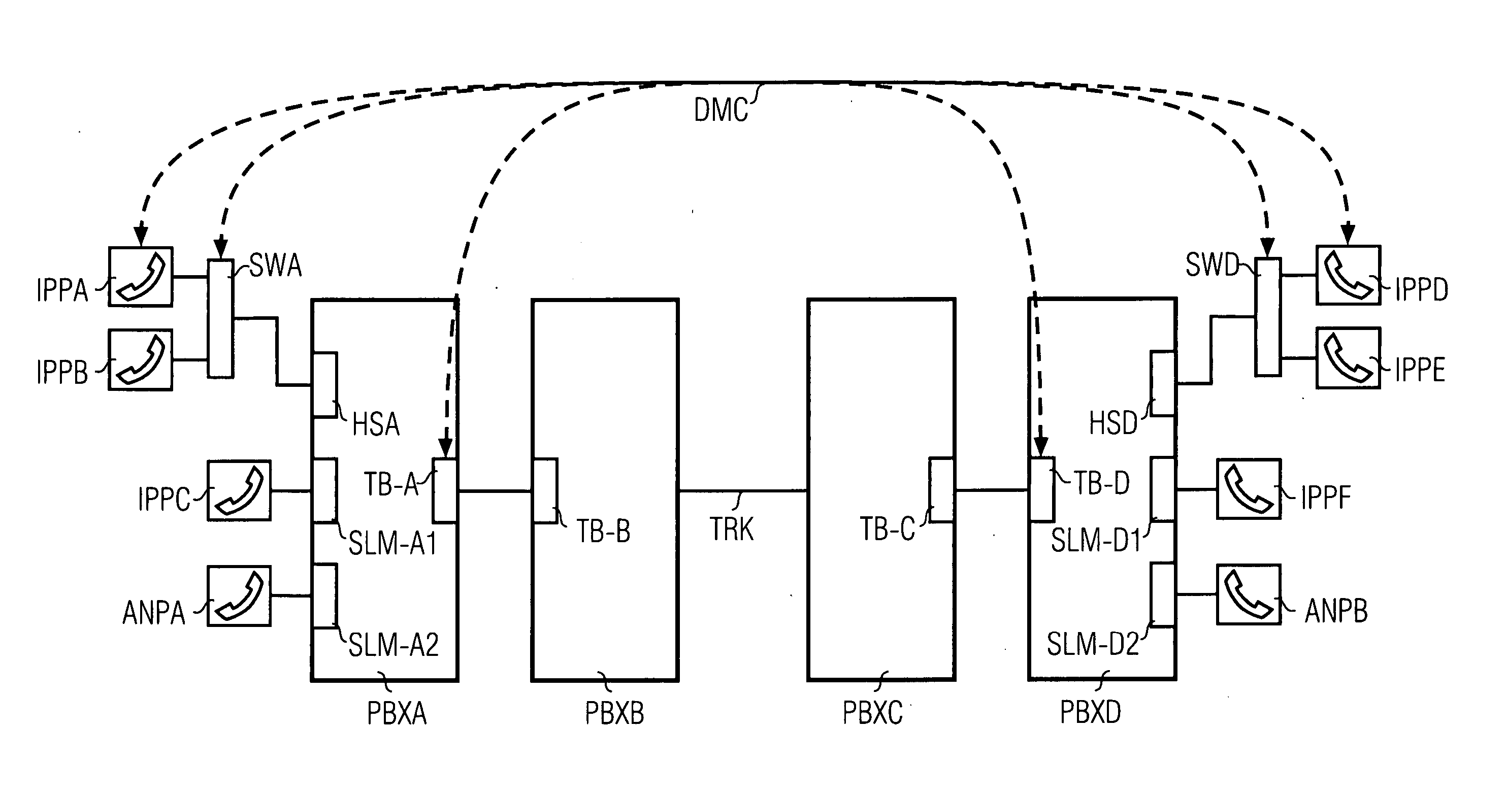
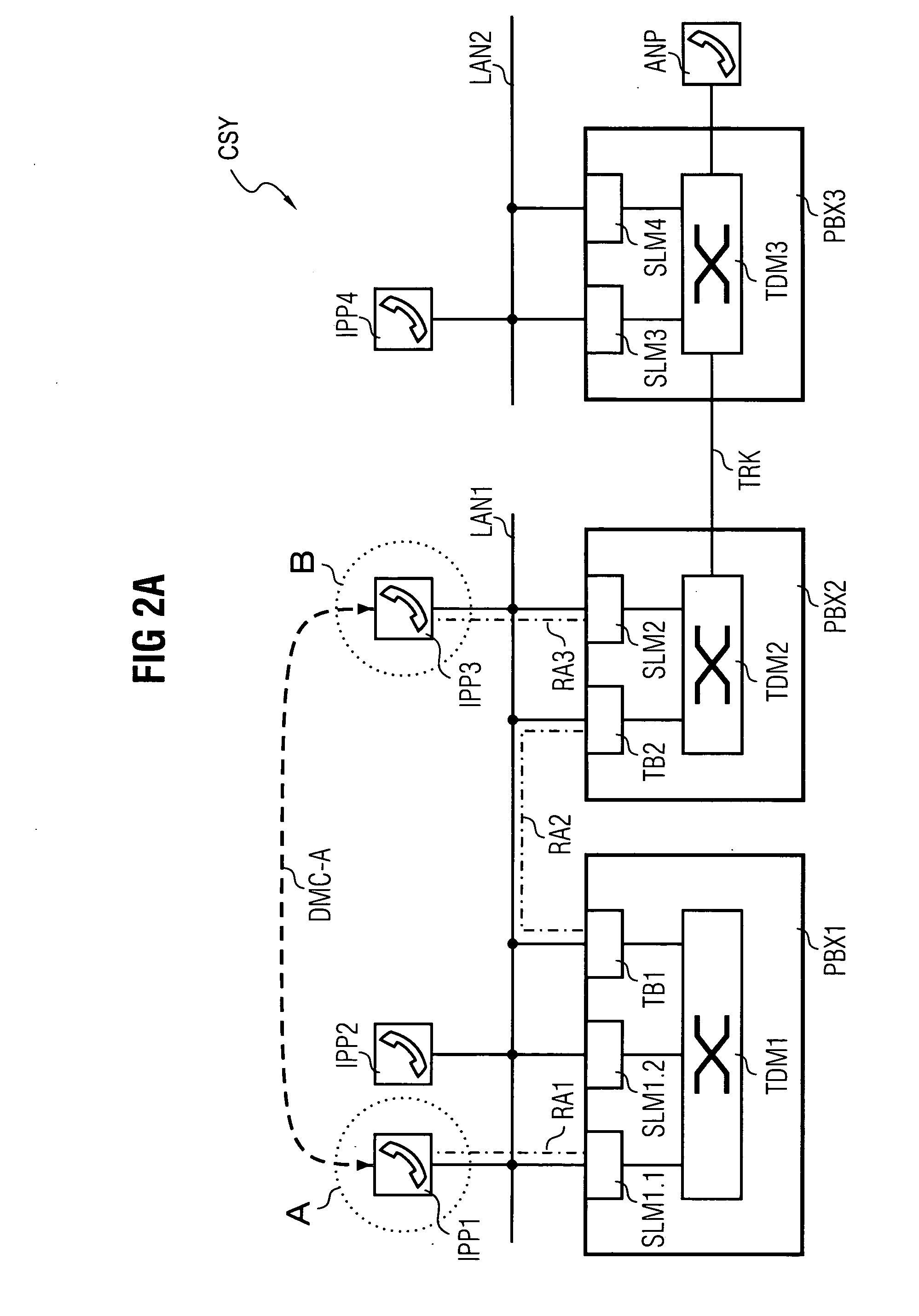
[0016] A significant advantage of the method according to the invention is to be seen in the fact that a transmission of communication data via the secondary connection is effected directly, that is to say without the involvement of a plurality of node units and consequently necessary conversions. The secondary connection is realized here for example via a packet-oriented network, as a result of which a multiple conversion of the user data packets or, as the case may be, user data stream in a heterogeneous communication system comprising both node units operating according to a circuit-switching transmission technology and node units operating according to a packet-oriented transmission technology is avoided in that a short path via the secondary connection is selected without an involvement of a plurality of node units.
[0017] A further advantage of the method according to the invention consists in the choice of the ingress or, as the case may be, egress node. In the method according to the invention it is provided here that the ingress node is located as near as possible to the calling first communication unit and, analogously, the egress node is located as near as possible to the called second communication unit. In a choice of a packet-oriented transmission method for the secondary connection, multiple conversions along the length of the secondary connection can thus be avoided. The packet-oriented transmission method is maintained without any further conversion along the secondary connection as far as the egress node. In a transmission of communication data, for example in the form of voice, a substantial improvement in the voice quality both at the calling first and the called second communication unit can be observed as a result of the use of the method according to the invention.
[0019] After the setup of the secondary connection the latter is advantageously maintained in addition to the primary connection. While communication data can be exchanged between the ingress and the egress node via the secondary connection, whereby this exchange produces a rise in quality in the above-described manner in particular in an exchange of user data, the primary connection maintained in parallel offers the advantage that in the event of a change in the call processing status, e.g. in the event of an inquiry call initiated by the calling subscriber, a switching-oriented controller of the node units, in particular communication devices, involved in the primary connection can be called upon in order to execute a corresponding service feature such as the inquiry call mentioned.

Problems solved by technology

As a result of the use of packet-oriented data transmission methods for communication systems of this type there are frequently losses in the quality of the user data to be transmitted, which losses are due primarily to an alternating conversion between a continuous user data stream and user data packets.
Said multiple conversions result in a loss in quality of the user data to be transmitted between the two communication terminals taking part in the connection.

Method used


Image

  • Method for transmitting communication data in a communication system
  • Method for transmitting communication data in a communication system
  • Method for transmitting communication data in a communication system

Examples


Embodiment Construction

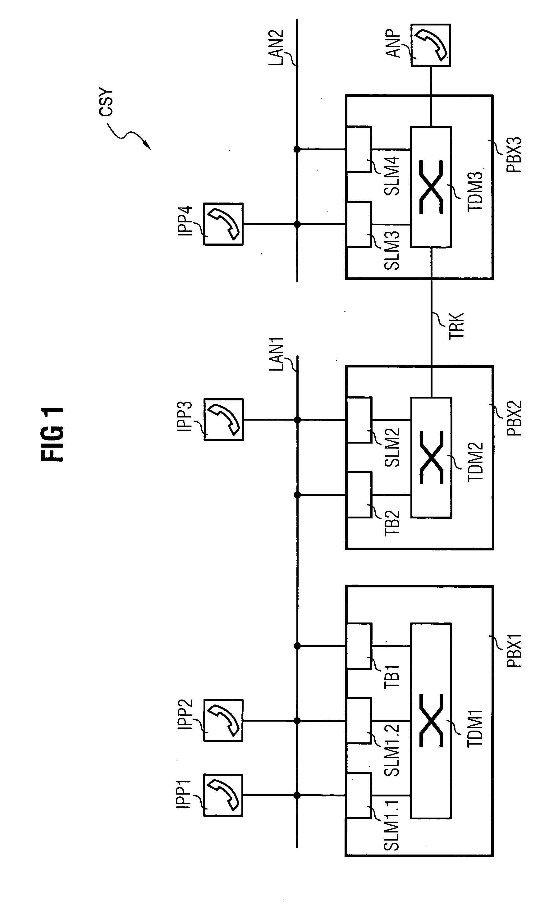
[0035]FIG. 1 shows a communication system CSY comprising an extract of functional components essential to the invention. Node units in the form of a first communication device PBX1, a second communication device PBX2 and a third communication device PBX3 are a major component of the communication system CSY.

[0036] The communication devices PBX1,PBX2,PBX3 operate internally according to a timeslot-oriented switching principle—often referred to in technical circles as >>Time Division Multiplex1,TDM2,TDM3.

[0037] The communication devices PBX1,PBX,PBX3 are in each case embodied with a circuit-switching switching matrix TDM1,TDM2,TDM3 and in each case connected both to one another and to a packet-oriented network.

[0038] The first and the second communication device PBX1,PBX2 are connected to a first packet-oriented network segment LAN1. The first packet-oriented network segment LAN1 is embodied alternatively as an intranet, corporate network, as a domain of a larger network or also as...


PUM


Abstract

The invention relates to a method for transmitting communication data in a communication system (CSY) between a calling first communication unit (IPPA) and a called second communication unit (IPPD), wherein, in a first step a primary connection is set up starting from the first communication unit (IPPA) via at least one node unit to the second communication unit (IPPD) with transmission of addressing data of the communication units (IPPA,IPPD) and node units participating in the setup of the primary connection. Following this, the first communication unit (IPPA) and / or a first node unit disposed along the primary connection which have a valid addressing data element are registered as the ingress node. Furthermore, the second communication unit (IPPD) and / or a last node unit disposed along the primary connection which have a valid addressing data element are registered as the egress node. With the embodiment of a secondary connection (DMC) between the egress and the ingress node via a network which is available in the communication system (CSY), communication data is finally transmitted via the secondary connection (DMC).

Description

CROSS REFERENCE TO RELATED APPLICATIONS [0001] This application claims priority to the German application No. 10354947.1 DE, filed Nov. 25, 2003 and which is incorporated by reference herein in its entirety. FIELD OF INVENTION [0002] The invention relates to a method for transmitting communication data in a preferably heterogeneous communication system. BACKGROUND OF INVENTION [0003] In contemporary communication systems it is known how to transmit user data, e.g. for voice or video communication, both by means of what is known as a circuit-switched technology and also via packet-oriented networks. Communication systems which support both a packet-oriented and a circuit-switching transmission technology are referred to in the following as >>convergent<< communication systems. As a result of the use of packet-oriented data transmission methods for communication systems of this type there are frequently losses in the quality of the user data to be transmitted, which losses...

Claims


Application Information

Patent Timeline
Patent Type & Authority Applications(United States)
IPC IPC(8): H04L29/06H04M7/00H04Q3/00
CPCH04M7/006H04M7/009H04M7/1245H04Q3/0016H04L65/80H04Q2213/13196H04Q2213/1322H04Q2213/13389H04L65/1069H04Q2213/13034
Inventor STAMPFL, ROBERTWILLE, KLAUSWINKLER, STEFFI
Owner UNIFY GMBH & CO KG
Learn More