Method for determining jitter of a signal in a serial link and high speed serial link

US20050111536A1Active Publication Date: 2005-05-26MARVELL ASIA PTE LTD

Image

  • Method for determining jitter of a signal in a serial link and high speed serial link
  • Method for determining jitter of a signal in a serial link and high speed serial link
  • Method for determining jitter of a signal in a serial link and high speed serial link

Examples


Embodiment Construction

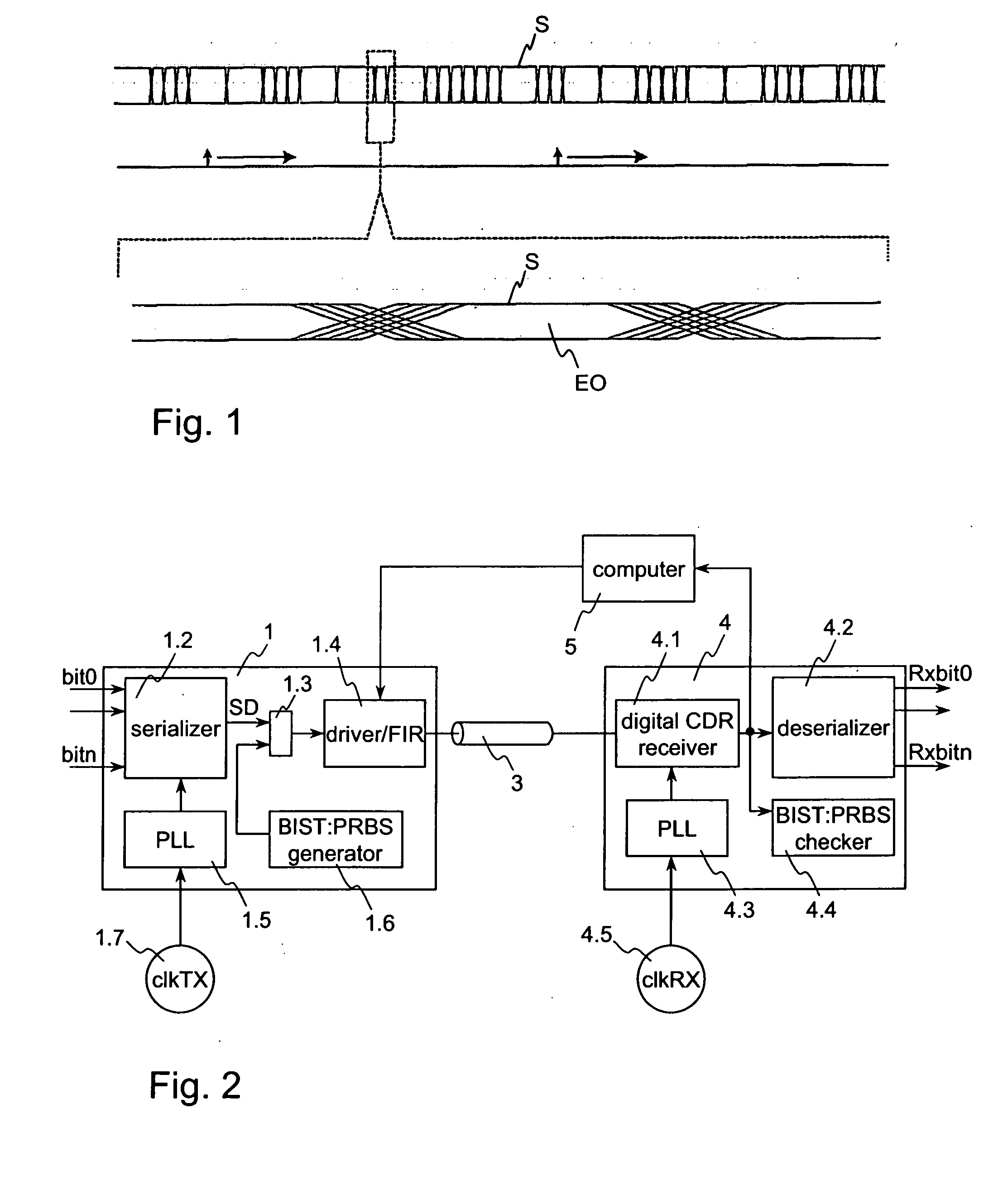
[0059]FIG. 1 shows a timing diagram of a data signal and below an enlarged part thereof showing the jitter during the falling and raising signal edges. FIG. 1 and the illustrated jitter are already described in the section “Background of the invention”.

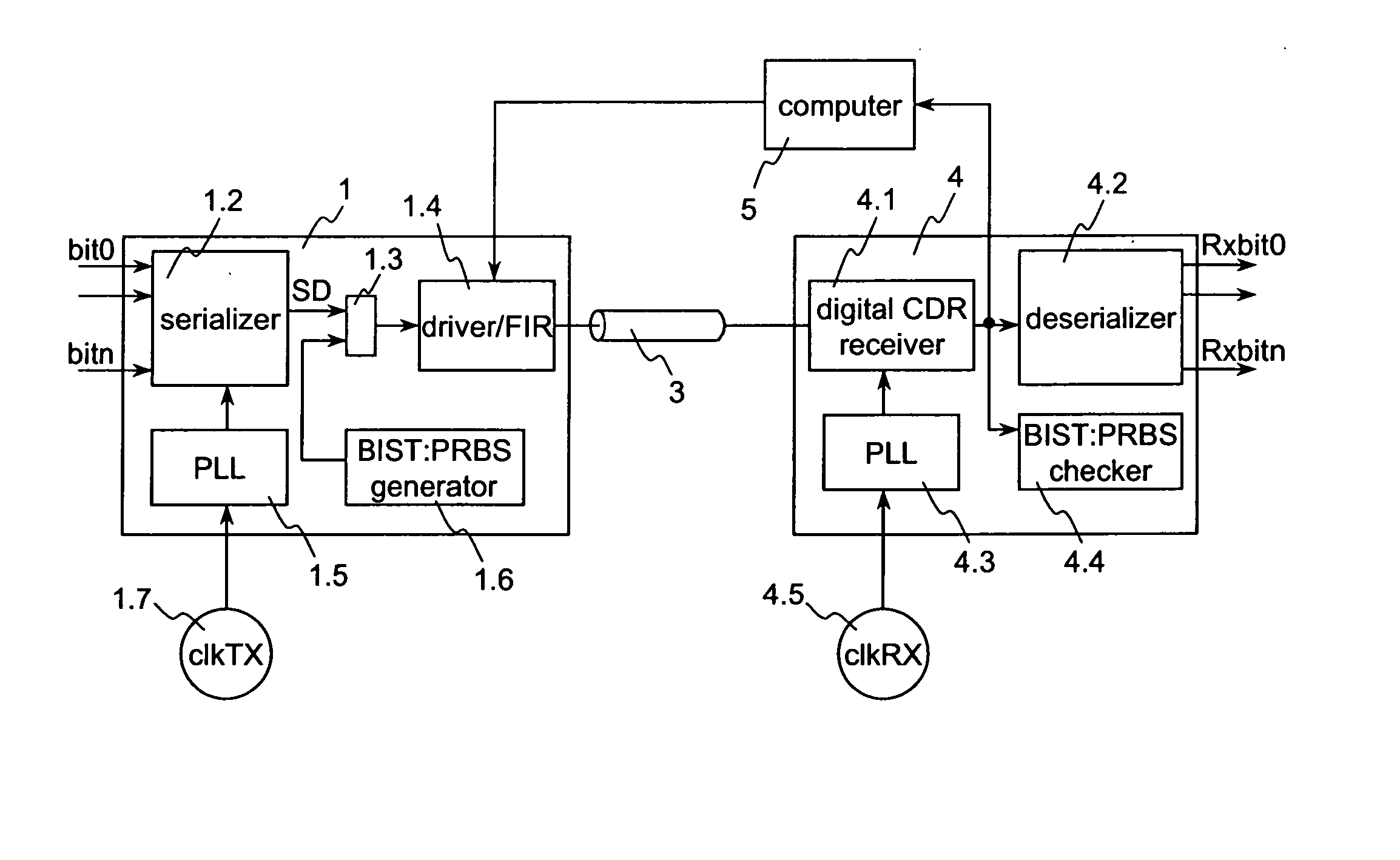
[0060]FIG. 2 shows a block diagram of a serial link. The link comprises a transmitter 1, a receiver 4 and a transmission line 3 connected between the transmitter 1 and the receiver 4.

[0061] When the serial link works as synchronous serial link the clock clkTX on the transmission side and the clock clkRX on the receiver side are synchronized, this means clkTX=clkRX. However, when the serial link works as asynchronous serial link both clocks clkTX and clkRX are not synchronized, this means clkTX≠clkRX. Independent from the mode—synchronous or asynchronous—in which the serial link is operated the method according to the invention can be used to determine the jitter even during user data are transmitted.

[0062] The transmission line or ...


PUM


Abstract

The method for determining jitter of a signal in a serial link according to the invention comprising the following steps: First, a section of the signal transmitted via a transmission channel is sampled at different sampling times. The total number of edges in the section is determined. The neighboring sample values are analyzed and from that a statistical value is formed. From the statistical value and the total number of edges a figure of merit is determined. Finally, by means of a look-up table or a jitter-versus-figure of merit curve, the total jitter corresponding to the figure of merit is derived.

Description

TECHNICAL FIELD [0001] The present invention relates to a high speed serial link and to a method for determining jitter of a signal in the high speed serial link. BACKGROUND OF THE INVENTION [0002] A general definition of jitter means that jitter is a measure of the time deviation that the waveform exhibits at its significant instants from a ideal reference. In a digital signal, the significant instants are the transition points. The reference can be generated from the sampled data or is externally provided. [0003] In the upper part of FIG. 1 the timing diagram of a data signal S is illustrated. Below the course of the data signal S an enlarged part of a part of the data signal is shown. As it can be seen, due to the jitter the points of time at which the state of the signal changes cannot exactly be defined and the bigger the jitter gets, the smaller the eye opening EO gets. [0004] The sources of jitter can be grouped into three categories. The first category includes all random no...

Claims


Application Information

Patent Timeline
26 May 2005
Publication
US20050111536A1
IPC
H04B3/46; H04L1/20; H04L25/06
CPC
H04B3/462; H04L25/068; H04L1/205
Inventors
CRANFORD, HAYDEN C. JR.; KOSSEL, MARCEL A.