Stationary computed tomography system and method

Active Publication Date: 2005-05-26
GENERAL ELECTRIC CO
View PDF14 Cites 152 Cited by
  • Summary
  • Abstract
  • Description
  • Claims
  • Application Information

AI Technical Summary

Benefits of technology

[0006] The present invention provides novel geometries and configurations for computed tomography (CT) systems designed to respond to such needs. The technique may be applied in a wide range of settings, including medical diagnostics conte

Problems solved by technology

While such arrangements have proven extraordinarily useful in identifying features of intere

Method used


Image

  • Stationary computed tomography system and method
  • Stationary computed tomography system and method
  • Stationary computed tomography system and method

Examples


Embodiment Construction

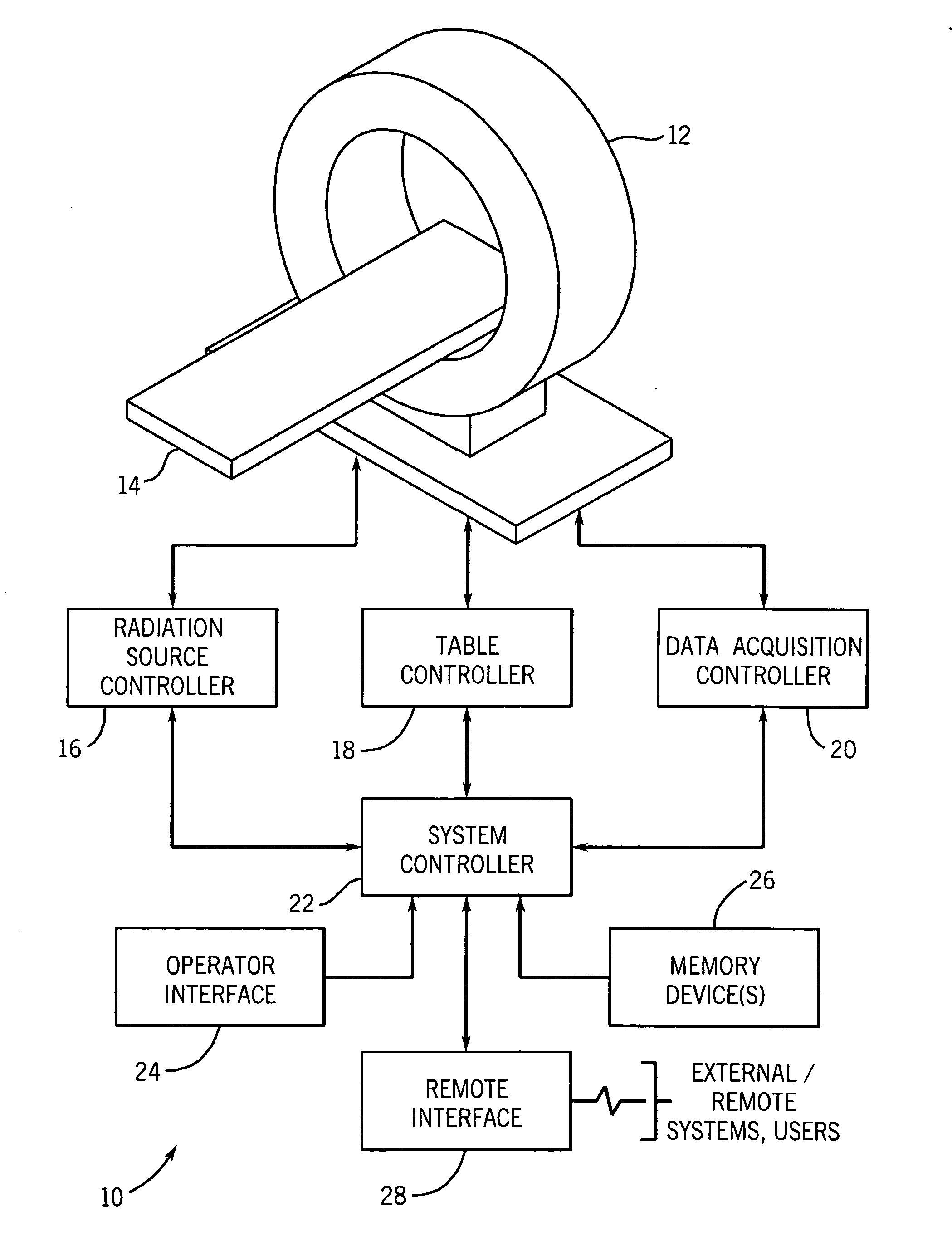
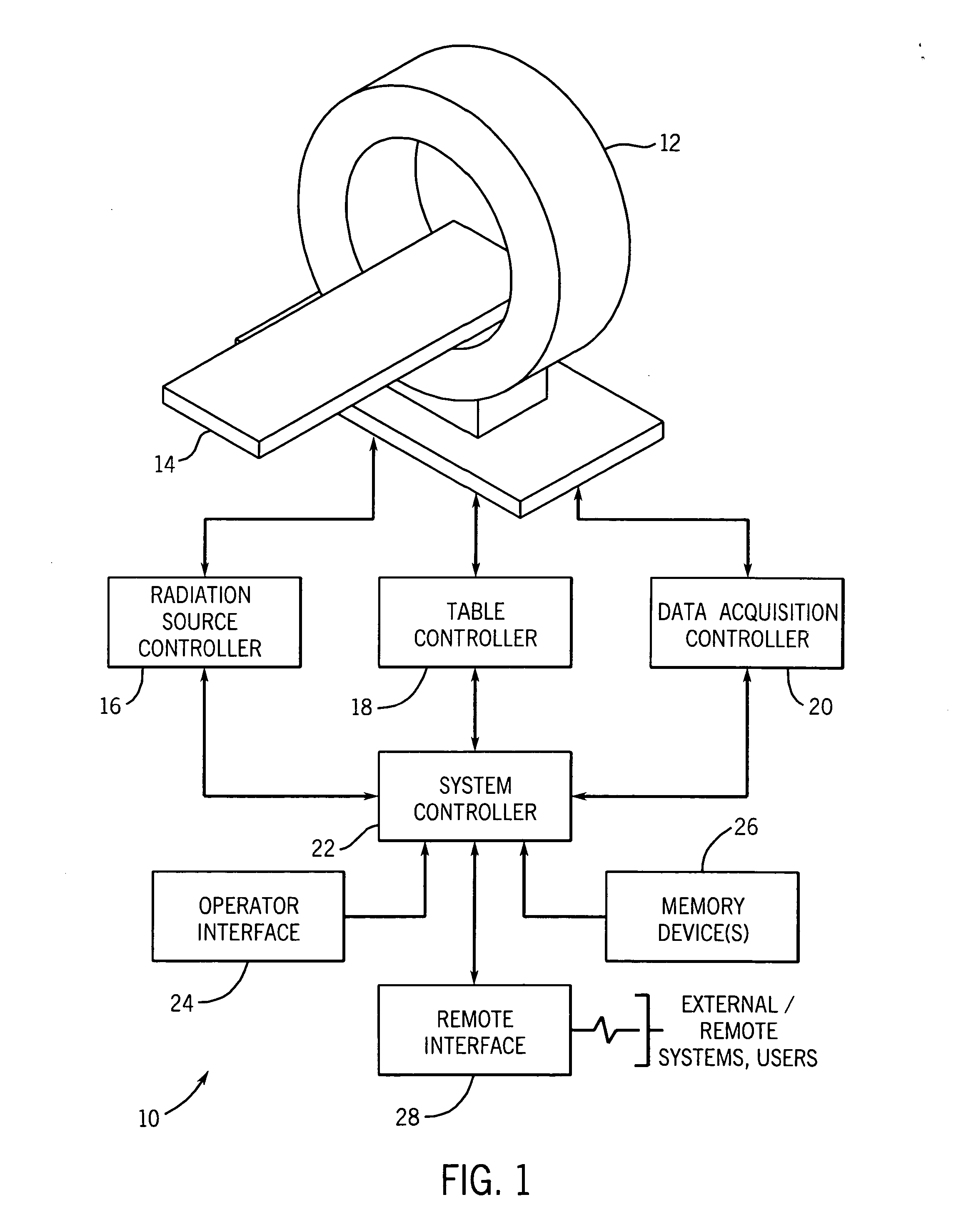
[0039] Turning now to the drawings, referring first to FIG. 1, a stationary computed tomography (CT) system is illustrated and designated generally by reference numeral 10. The CT system 10 comprises a scanner 12 formed of a support structure and internally containing one or more stationary and distributed sources of X-ray radiation (not shown in FIG. 1) and one or more stationary digital detectors (not shown in FIG. 1), as described in greater detail below. The scanner is configured to receive a table 14 or other support for a patient, or, more generally, a subject to be scanned. The table can be moved through an aperture in the scanner to appropriately position the subject in an imaging volume or plane scanned during imaging sequences.

[0040] The system further includes a radiation source controller 16, a table controller 18 and a data acquisition controller 20, which may all function under the direction of a system controller 22. The radiation source controller 16 regulates timin...


PUM


Abstract

Configurations for stationary imaging systems are provided. The configurations may include combinations of various types of distributed sources of X-ray radiation, which generally include addressable emitter elements which may be triggered for emission in desired sequences and combinations. The sources may be ring-like, partial ring-like, or line-like (typically along a Z-axis), and so forth. Combinations of these are envisaged. Corresponding detectors may also be full ring detectors or partial ring detectors associated with the sources to provide sufficient coverage of imaging volumes and to provide the desired mathematical completeness of the collected data.

Description

CROSS REFERENCE TO RELATED APPLICATIONS [0001] This application is related to Provisional Application U.S. Ser. No. 60 / 525,587, Attorney Docket No. 127068-1, filed Nov. 26, 2003 in the U.S. Patent and Trademark Office, the contents of which are incorporated herein by reference, and the benefit of priority to which is claimed under 35 U.S.C. 119(e).BACKGROUND OF THE INVENTION [0002] The present invention relates generally to the field of computed tomography imaging systems. More particularly, the invention relates to geometries and configurations for the stationary computed tomography systems in which a detector and distributed source element are fixedly positioned in an imaging system scanner. [0003] Many applications exist for computed tomography imaging systems. Developed over recent decades, such imaging systems provide a powerful tool for imaging internal features of subjects of interest, typically presented as slices and volumes. In general, the systems consist of a source that...

Claims


Application Information

Patent Timeline
IPC IPC(8): A61B6/03G01N23/04G01T1/29
CPCA61B6/03A61B6/032A61B6/4014G01N2223/419G01N23/046G01T1/2985A61B6/027A61B6/4275
Inventor DE MAN, BRUNO KRISTIAAN BERNARDBASU, SAMIT KUMAREDIC, PETER MICHAELSENZIG, ROBERT FRANKLINROSS, WILLIAM ROBERTWU, XIAOYEWILSON, COLIN RICHARDVERMILYEA, MARK ERNESTSARAGNESE, EUGENE LINO
Owner GENERAL ELECTRIC CO
Why Eureka
Try Eureka