
Apparatus for vehicle surroundings monitoring and method thereof

a technology for vehicle surroundings and apparatus, applied in scene recognition, television systems, instruments, etc., can solve the problems of difficult to improve the degree of accuracy, inability to distinguish between a pedestrian and an object having a similar vertical dimension to that of a pedestrian and a temperature similar, etc., and achieve the effect of low cost and high degree of accuracy

Inactive Publication Date: 2005-05-26
NISSAN MOTOR CO LTD
View PDF1 Cites 70 Cited by
  • Summary
  • Abstract
  • Description
  • Claims
  • Application Information

AI Technical Summary

Benefits of technology

[0007] The present invention was conceived in view of these problems and its object is to provide a vehicle surroundings monitoring device that detects pedestrians with a high degree of accuracy and is low in cost.

Problems solved by technology

Although the technologies disclosed in Japanese Laid-Open Patent Publication No. 2001-6069 and Japanese Laid-Open Patent Publication No. 2001-108758 are capable of detecting objects that emit infrared rays, these technologies have suffered from the problem of detecting objects other than pedestrians.
More particularly, these technologies are unable to distinguish between a pedestrian and an object having a similar vertical dimension to that of a pedestrian and a temperature similar to the body temperature of a pedestrian.
Furthermore, when an attempt is made to extract pedestrians from among the detected objects by merely employing such a shape identification method as checking the ratio of the vertical dimension to the horizontal dimension, it is difficult to improve the degree of accuracy.
Stereo infrared cameras are necessary to perform the distance measurements for setting the template and, consequently, the device becomes very expensive.
Furthermore, the template matching processing creates a heavy computer processing load and it becomes necessary to use a high-speed CPU (central processing unit) and a special DSP (digital signal processor), again causing the device to be expensive.
Additionally, since it is not possible to prepare templates that cover all of the possible patterns of structures that actually exist, structures that do not match any of the templates used for comparison with extracted objects are recognized as pedestrians, thus causing the degree of accuracy with which pedestrians are detected to be low.

Method used


Image

  • Apparatus for vehicle surroundings monitoring and method thereof
  • Apparatus for vehicle surroundings monitoring and method thereof
  • Apparatus for vehicle surroundings monitoring and method thereof

Examples


embodiment 1

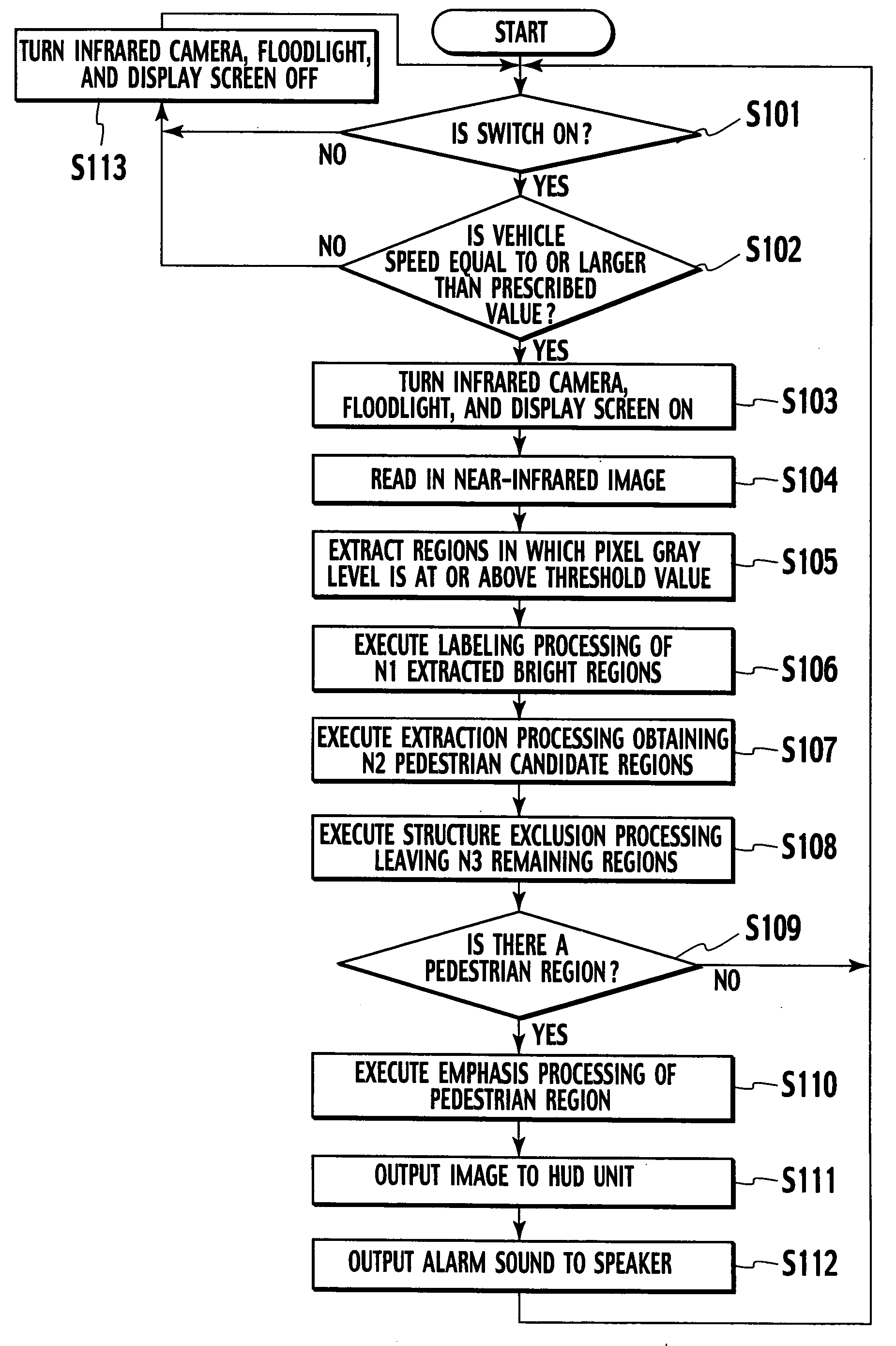
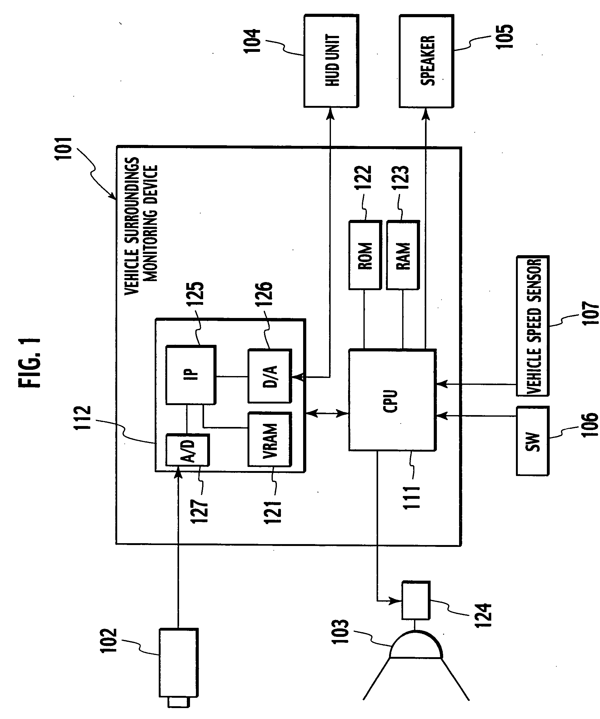
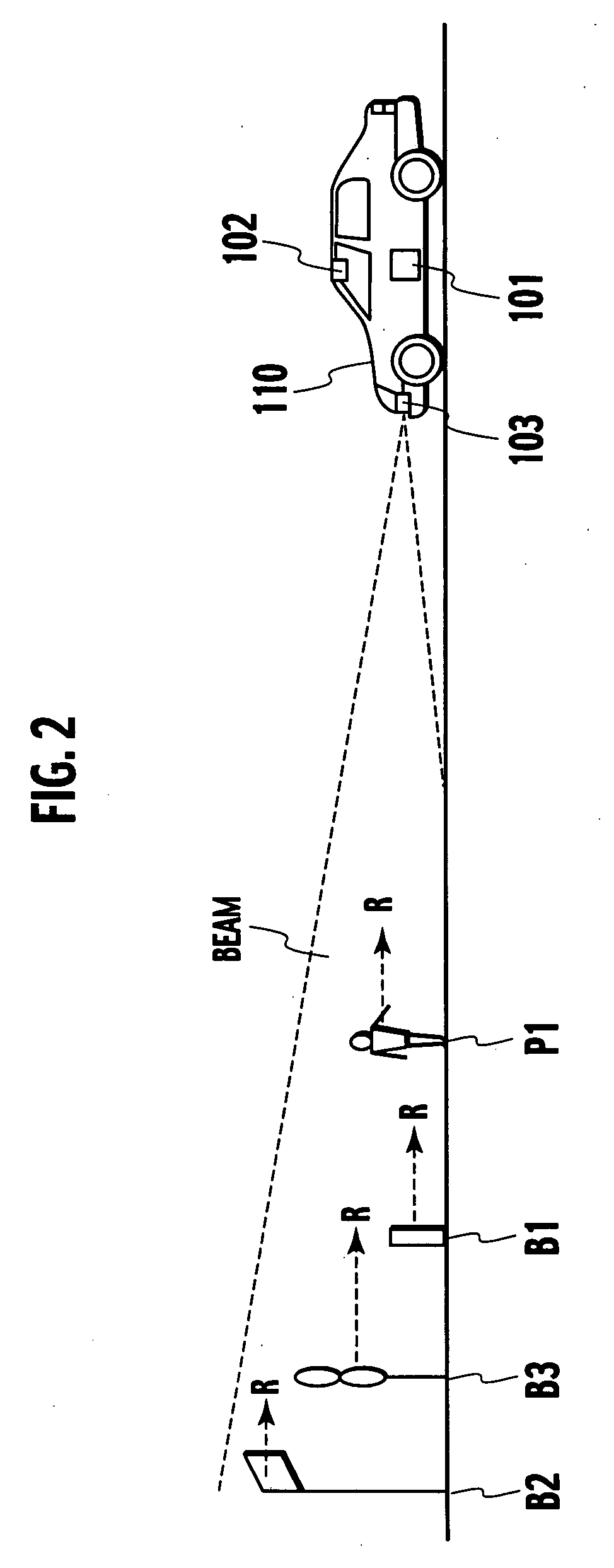
[0023]FIG. 1 is a block diagram showing an embodiment of a vehicle surroundings monitoring device in accordance with the present invention. The vehicle surroundings monitoring device provided with a CPU 111 and an image processing unit 112 and is electrically coupled to the following: a switch relay 124 for a floodlight 103 configured to illuminate a prescribed region range in front of the vehicle with light having a near-infrared wavelength; an infrared camera 102 capable of detecting near infrared light; a switch (SW) 106 configured to turn the function of the vehicle surroundings monitoring device 101 on and off; and a vehicle speed sensor 107 configured to detect the traveling speed of the vehicle in which the vehicle surroundings monitoring device 101 is installed (hereinafter called “vehicle speed”).

[0024] The vehicle surroundings monitoring device 101 is also electrically coupled to a speaker 105 for emitting alarm sounds and a head-up display unit (hereinafter called “HUD u...


PUM


Abstract

An aspect of the present invention provides a vehicle surroundings monitoring device that includes an object extracting unit configured to extract objects that emit infrared rays from a photographed infrared image, a pedestrian candidate extracting unit configured to extract pedestrian candidates based on the shape of the images of objects extracted by the object extracting unit, and a structure exclusion processing unit configured to exclude structures from the pedestrian candidates based on the gray levels of the images of the pedestrian candidates.

Description

BACKGROUND OF THE INVENTION [0001] The present invention relates to a vehicle surroundings monitoring device configured to detect pedestrians existing in the vicinity of the vehicle. [0002] Japanese Laid-Open Patent Publication No. 2001-6069 discloses vehicle surroundings monitoring device configured to detect a pedestrian existing in the vicinity of the vehicle using an infrared image photographed with a photographing means provided on the vehicle. The vehicle surroundings monitoring device described in that publication calculates the distance between the vehicle and an object located in the vicinity of the vehicle using images obtained from two infrared cameras and calculates the motion vector of the object based on position data found using a time series. Then, based on the direction in which the vehicle is traveling and the motion vector of the object, the device detects if there is a strong possibility of the vehicle colliding with the object. [0003] Japanese Laid-Open Patent P...

Claims


Application Information

Patent Timeline
IPC IPC(8): B60R1/00B60R21/34G01V8/10G06K9/00G06K9/82G06T1/00G06T7/00G08G1/16H04N5/33H04N7/18
CPCB60R1/00B60R2300/103B60R2300/106B60R2300/205B60R2300/30B60R2300/302G06K9/00805B60R2300/404B60R2300/60B60R2300/8033B60R2300/8053G06K9/00369H04N5/33B60R2300/305G06V40/103G06V20/58B60R1/30B60R1/24H04N23/20
Inventor KAWAI, AKIO
Owner NISSAN MOTOR CO LTD
Learn More