Transmission loss and gain measurement method, transmitter-receiver, and transmitting-receiving system

a technology of loss and gain measurement and transmitter, which is applied in the field of communication transmission receivers, can solve the problems of optical transmission receivers that do not have functions, optical transmission receivers are disabled for communication, and conventional optical transmission receivers have problems

Active Publication Date: 2005-05-26
NEC CORP
View PDF4 Cites 63 Cited by
  • Summary
  • Abstract
  • Description
  • Claims
  • Application Information

AI Technical Summary

Benefits of technology

[0009] It is therefore an object of the present invention to provide a transmitter-receiver having a means for automatically determining the status of transmission me...

Problems solved by technology

The conventional optical transmitter-receiver, however, has some problems.
First, the transmitter-receiver does not have a function for automatically setting the transmission rate according to the status of a channel or the like.
Therefore, when the transmission loss is increased to a certain value, the optical transmitter-receiver is disabled for communication.
In other words, even when data can be communicated by reducing the transmission rate, the optical transmitter-receiver cannot adjust a transmis...

Method used


Image

  • Transmission loss and gain measurement method, transmitter-receiver, and transmitting-receiving system
  • Transmission loss and gain measurement method, transmitter-receiver, and transmitting-receiving system
  • Transmission loss and gain measurement method, transmitter-receiver, and transmitting-receiving system

Examples


first embodiment

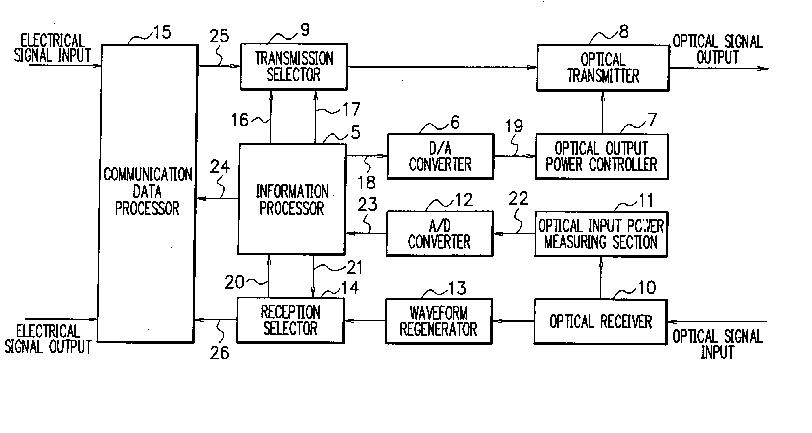
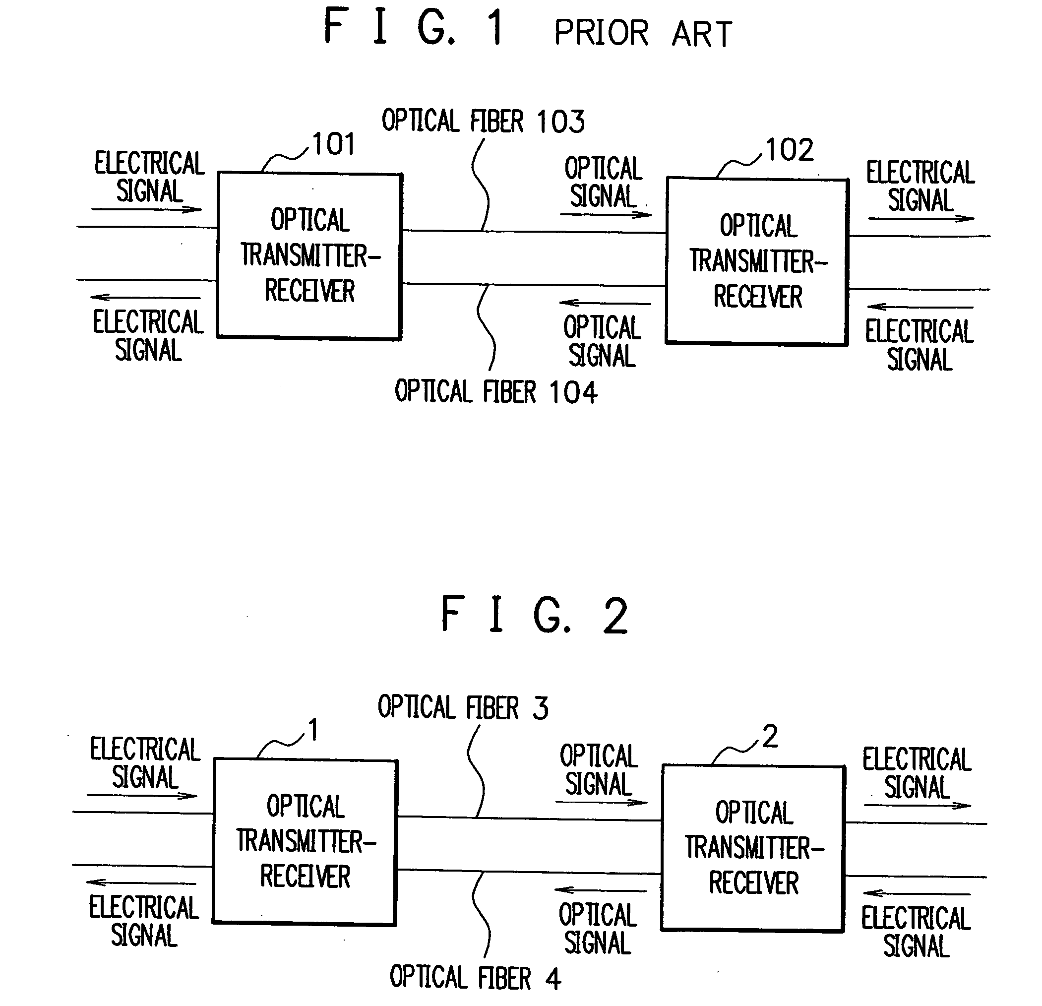
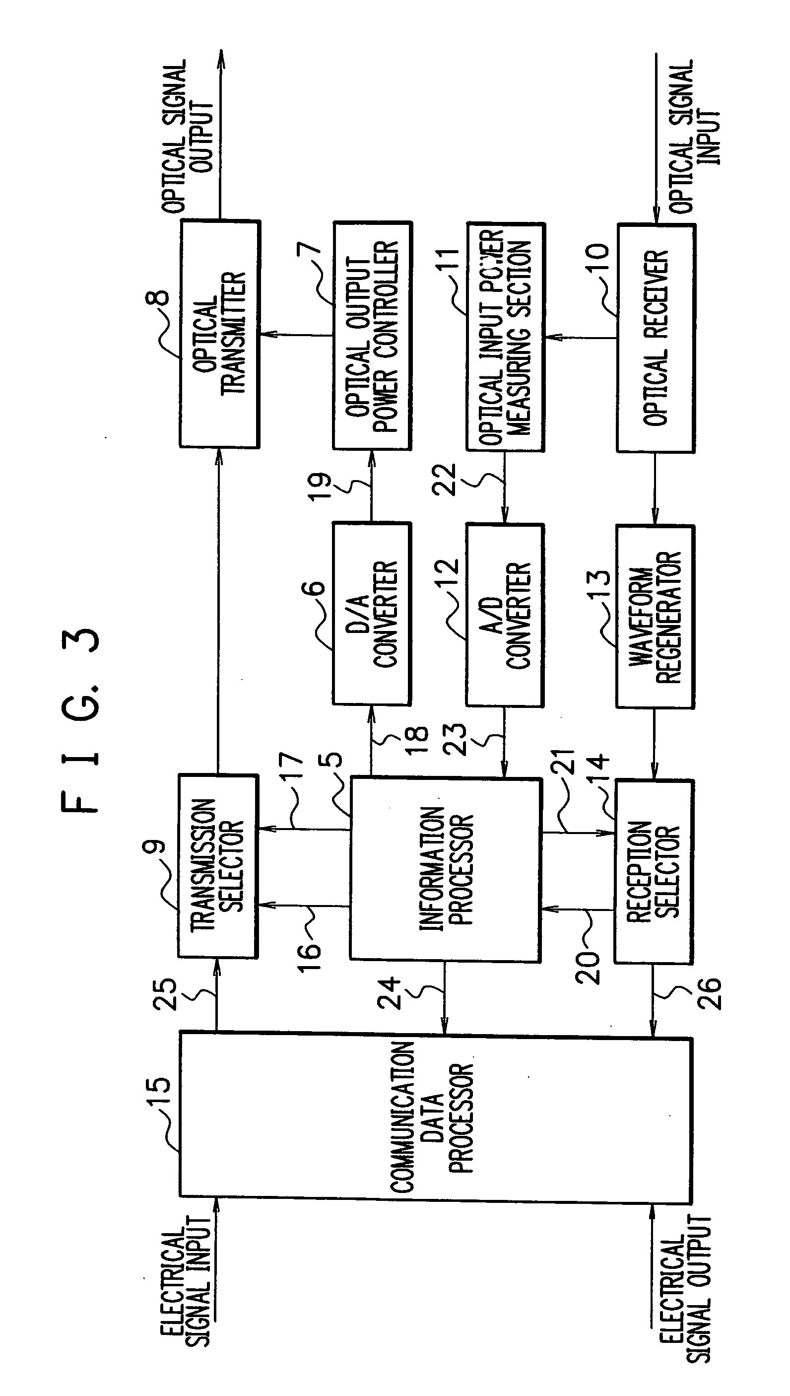
[0061]FIG. 3 is a block diagram showing the construction of the optical transmitter-receiver according to the present invention. The optical transmitter-receivers 1 and 2 in FIG. 2 are of like construction and thus but one of them is shown in FIG. 3. As can be seen in FIG. 3, the optical transmitter-receiver comprises an information processor 5, a digital-analog (D / A) converter 6, an optical output power controller 7, an optical transmitter 8, a transmission selector 9, an optical receiver 10, an optical input power measuring section 11, an analog-digital (A / D) converter 12, a waveform regenerator 13, a reception selector 14, and a communication data processor 15.

[0062] The optical transmitter 8 converts an electrical signal to an optical signal to output the optical signal. The optical output power controller 7 controls the optical output power of the optical transmitter 8. The optical receiver 10 converts an input optical signal to an electrical signal. The optical input power mea...

third embodiment

[0122] the communication data TDM separator 44 is provided with a plurality of the I / O ports 45-1 to45-10 as can be seen in FIG. 17. The TDM processor 47 time-division multiplexes signals from the first to tenth I / O ports 45-1 to 45-10, and produces a serial signal. Thereby, the optical transmitter-receiver can transmit signals as a serial signal to the other optical transmitter-receiver. Thus, transmission can be performed more efficiently as compared to the case where signals are transmitted individually. Moreover, the optimum number of multiplexing is determined according to the size of the path loss, and therefore, transmission can be carried out effectively and sensibly.

[0123] Incidentally, while in the first to third embodiments, transmitter-receivers are connected via optical fibers as transmission media, the optical fibers are given merely by way of example and without limitation. The transmitter-receivers may be connected through other transmission media such as electrical...


PUM


Abstract

A transmitter-receiver having, a means for automatically determining the status of transmission medium such as optical fiber, and a means for automatically setting and resetting the transmission rate and/or output power according to the status of the transmission medium, a transmission loss and gain measurement method, and a transmitting-receiving system. A transmitter-receiver comprises at least: an output power controller for controlling the output power of a transmitter; an input power measuring section for measuring the strength of input signals; and an information processor for deriving the loss or gain of a path to change the output power of the transmitter and/or the rate of data transmission according to the derived loss or gain of the path. A transmission loss and gain measurement method applied to a system comprising transmission media and a plurality of the transmitter-receivers connected via the transmission media, comprises the steps of: transmitting information on the output power of a first transmitter-receiver from the first transmitter-receiver to a second transmitter-receiver; measuring reception strength by the second transmitter-receiver when the second transmitter-receiver receives the output power information; reading the output power information by the second transmitter-receiver; and comparing the reception strength with the output power information to calculate a transmission loss or gain by the second transmitter-receiver.

Description

FIELD OF THE INVENTION [0001] The present invention relates to a transmitter-receiver for communication, and more particularly, to a transmitter-receiver having a means for determining the status of a channel so as to be capable of selecting and changing the transmission rate and output power for transmission / reception according to the status of the channel, a transmission loss and gain measurement method, and a transmitting-receiving system. BACKGROUND OF THE INVENTION [0002] In general, data is transmitted and received between two opposed transmitter-receivers via transmission media. FIG. 1 is a diagram showing an example of optical transmitter-receivers that transmit and receive optical signals through optical fibers as transmission media. In FIG. 1, optical transmitter-receivers 101 and 102 are connected via optical fibers 103 and 104 with each other. Electrical signals output from or input to the optical transmitter-receivers 101 and 102 are sent to or from other equipment such...

Claims


Application Information

Patent Timeline
IPC IPC(8): H04B10/07H04B3/46H04B3/48H04B10/077H04B10/079H04B10/2507H04B10/54H04B10/556H04B10/564H04B17/00
CPCH04B10/07955H04B10/077
Inventor TAKEUCHI, TAKESHITAJIMA, AKIOHARADA, SHIGEKAZUTANAKA, AKIHIROMAEDA, WAKAKO
Owner NEC CORP
Why Eureka
Try Eureka