Industrial robot with controlled flexibility and simulated force for automated assembly

a robot and automation technology, applied in the direction of electric programme control, program control, instruments, etc., can solve the problems of repetitive motion stress injuries and injuries, problems with maintaining quality, efficiency, job satisfaction and health, and the robot positioning accuracy is not that relevant by itsel

Active Publication Date: 2005-05-26
ABB RES LTD +1
View PDF9 Cites 77 Cited by
  • Summary
  • Abstract
  • Description
  • Claims
  • Application Information

AI Technical Summary

Benefits of technology

[0009] An industrial robot that has but is not limited to a robot controller, an end effector for holding a first work piece to be mated to a second work piece held at a location and orientation not precisely known to the robot controller, and a predetermined number of articulated joints, each joint having its own actuation device and motion measurement device.

Problems solved by technology

There are various advantages that a robotic assembly has over human assembly since manual labor is boring, fatiguing, and can cause repetitive-motion stress injuries and injuries resulting from the manipulation by the worker of heavy objects during assembly.
These effects on humans lead to problems with maintaining quality, efficiency, job satisfaction and health.
However, in assembly applications where the relative position between mating parts is of ultimate importance, the robot positioning accuracy by itself is not that relevant because the relative position of the parts is more important than their absolute position.
However, these passive devices lack a general utility, can not cover a large class of assembly tasks without resorting to another part specific device and do not actively position and rotate the mating parts relative to each other which gives longer assembly times, requirements on higher accuracy of the robot and a higher risk of a robot malfunction.
The accuracy obtained using motor torques and a robot model is not as good as the accuracy obtained using a force sensor.
At present, there does not exist a high level programming language nor an easy programming concept to exploit the force control capability.
In other words, successful force feedback control alone only tries to avoid high contact force, or separation tendency, and lacks a mechanism that would bond the parts together according to their geometrical contour.
For example in the assembly of a gear, while a force control enabled compliant robot would ensure that no jamming / galling would occur, it would not lead the robot toward a correct alignment of the mating pieces.
The conventional thinking of modifying the robot position based on the interaction force is cumbersome and difficult if not at all impossible to implement in the cases where the mating parts uncertainty is high and the combinations of possible parts contact situations are numerous and mathematically impossible to handle.

Method used


Image

  • Industrial robot with controlled flexibility and simulated force for automated assembly
  • Industrial robot with controlled flexibility and simulated force for automated assembly
  • Industrial robot with controlled flexibility and simulated force for automated assembly

Examples


Embodiment Construction

)

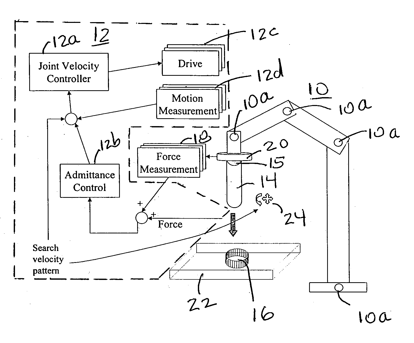
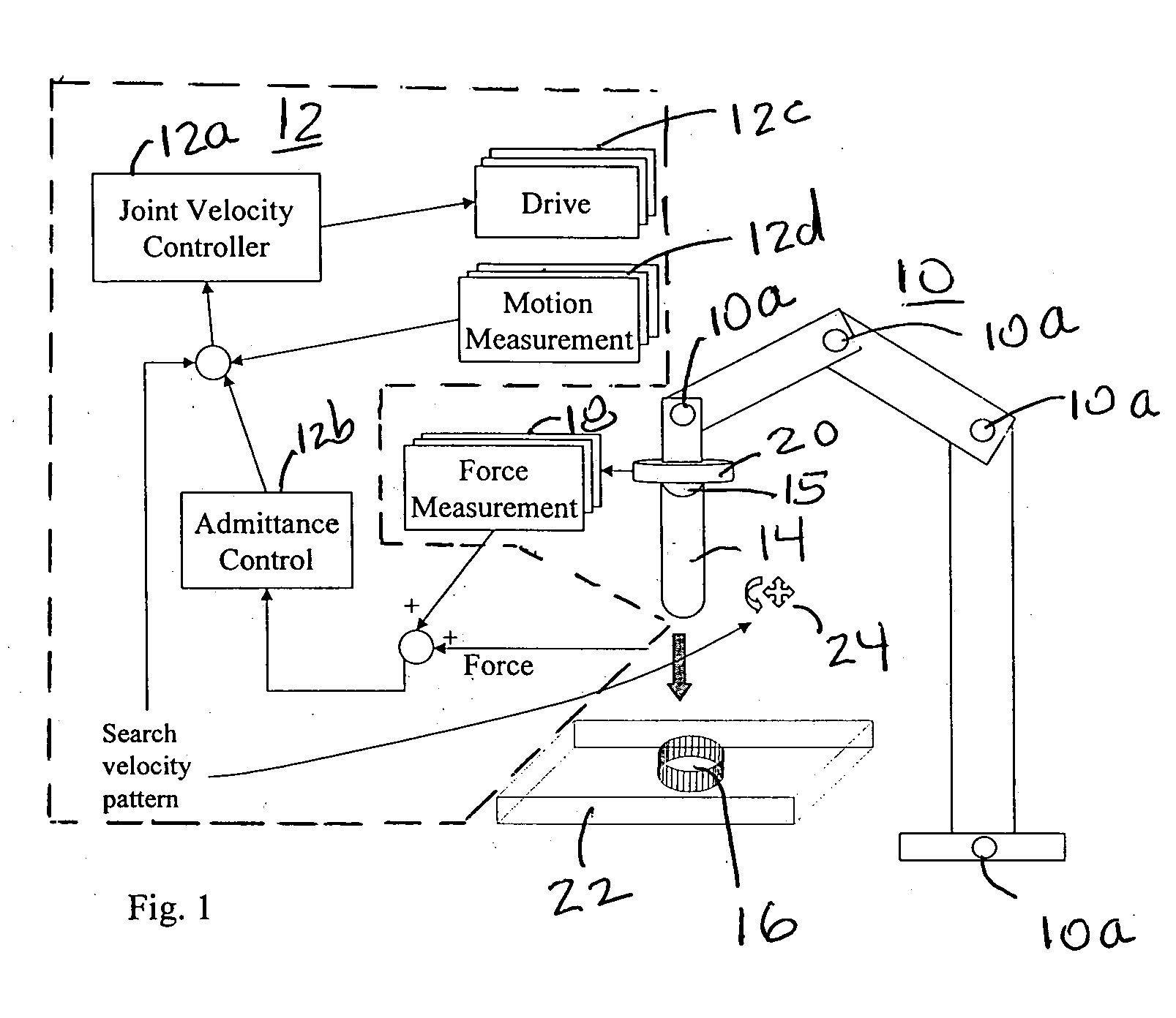
[0016]FIG. 1 illustrates a preferred embodiment of the robotic system that can be easily programmed for assembly tasks.

[0017] Shown in FIG. 1 is an articulated industrial robot 10 interfaced with a computer controller 12 where the method of the present invention is implemented. Computer controller 12 comprises joint velocity controller 12a, admittance control 12b and for each articulated joint 10a of robot 10 a mechanical actuation device or drive 12c and a motion measurement 12d. Not shown in FIG. 1 is the processor which is part of controller 12.

[0018] In a typical industrial robot, there are four to seven articulated joints and when controlled synchronously, the end-effector 15 of the robot 10 can move in a three dimensional task space and follow a pre-designed trajectory. As described above, each joint would have its own mechanical actuation device or drive 12c, typically a servomotor, and measurement device 12d, typically a resolver or encoder to measure the joint angle. The...


PUM


Abstract

An industrial robot that has uses a simulated force vector to allow a work piece held by the robot end effector to be mated with a work piece whose location and orientation is not precisely known to the robot. When the end effector makes contact with the location and orientation in which the other work piece is held the robot provides a velocity command to minimize the force of the contact and also provides a search pattern in all directions and orientations to cause the end effector to bring the work piece it is holding in contact with the other work piece. The search pattern and the velocity command are continued until the two work pieces mate.

Description

FIELD OF THE INVENTION [0001] This invention relates to methods and apparatus for automated assembly employing an industrial robot with controlled flexibility and system inherent simulated force to simplify machine assembly process. DESCRIPTION OF THE PRIOR ART [0002] In the last forty years, industrial robots have found a variety of uses in manufacturing automation. An important application domain for robotic automation that has lagged behind expectations is mechanical assembly and material removal processes. There are various advantages that a robotic assembly has over human assembly since manual labor is boring, fatiguing, and can cause repetitive-motion stress injuries and injuries resulting from the manipulation by the worker of heavy objects during assembly. These effects on humans lead to problems with maintaining quality, efficiency, job satisfaction and health. In those applications where a robot could perform the job, these considerations can make automation highly attract...

Claims


Application Information

Patent Timeline
Patent Type & Authority Applications(United States)
IPC IPC(8): B25J9/16
CPCB25J9/1633B25J9/1687G05B2219/36437G05B2219/39339Y10T74/20317G05B2219/40032G05B2219/45058Y10S414/136G05B2219/39529Y02P80/10
Inventor ZHANG, HUIGAN, ZHONGXUEBROGARDH, TORGNYWANG, JIANJUN
Owner ABB RES LTD
Why Eureka
Try Eureka