Method for controlling fuel splits to gas turbine combustor

a technology of combustor and fuel split, which is applied in the direction of machines/engines, lighting and heating apparatus, instruments, etc., can solve the problem that the conventional scheduling algorithm for dln combustion systems does not generally take into account variations

Active Publication Date: 2005-05-26
GENERAL ELECTRIC CO
View PDF9 Cites 38 Cited by
  • Summary
  • Abstract
  • Description
  • Claims
  • Application Information

AI Technical Summary

Problems solved by technology

Conventional scheduling algorithms for DLN combustion systems do not generally take into account variations in compressor inlet pressure loss, turbine back pressure, or compressor inlet humidity.

Method used


Image

  • Method for controlling fuel splits to gas turbine combustor
  • Method for controlling fuel splits to gas turbine combustor
  • Method for controlling fuel splits to gas turbine combustor

Examples


Embodiment Construction

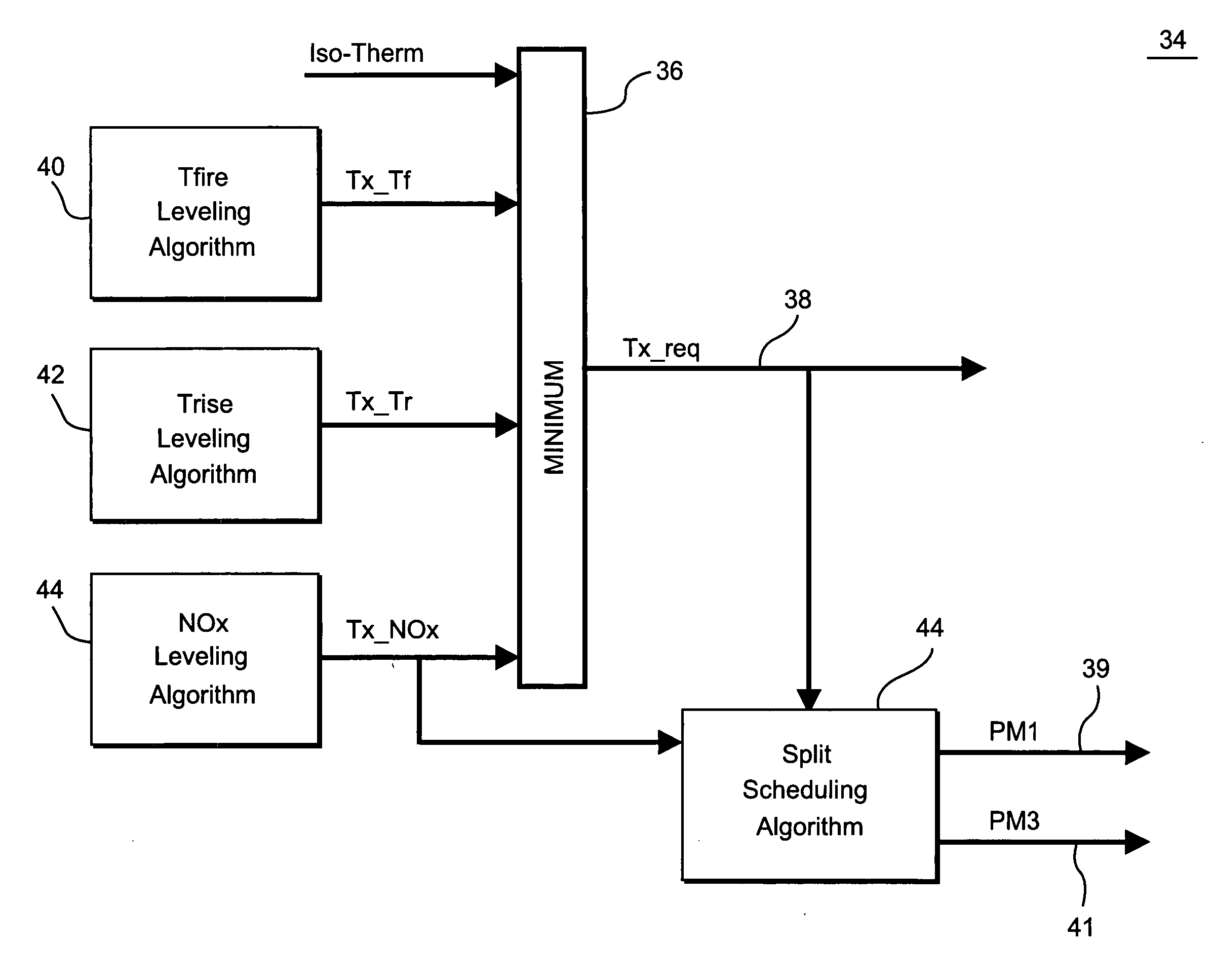
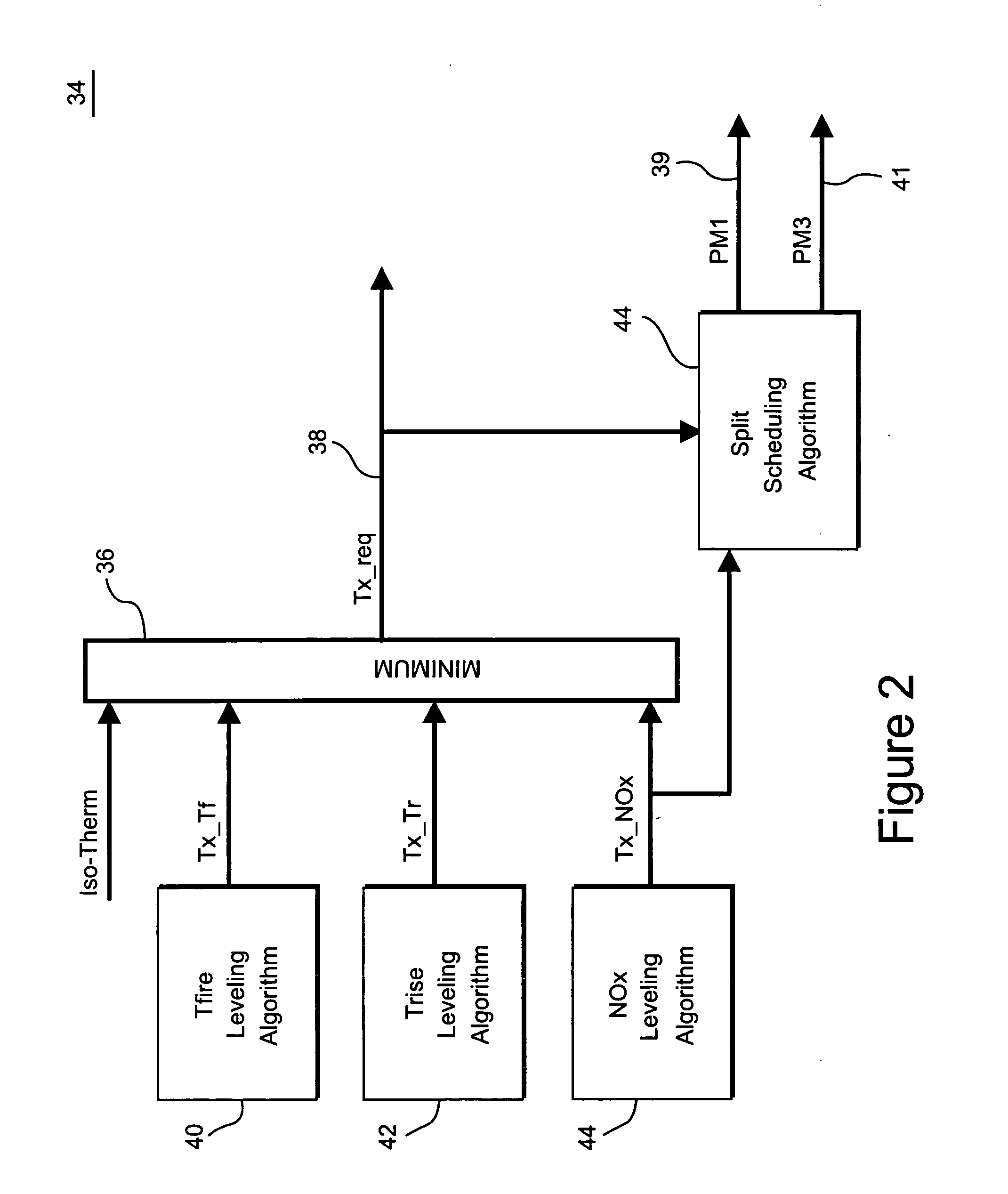
[0013] A gas turbine control system and method of algorithms has been developed to schedule the operation of a gas turbine such that the turbine exhaust temperature and combustor fuel splits are cooperatively scheduled. By linking algorithms for determining the turbine exhaust temperature and fuel splits, the gas turbine control system can simultaneously level the combustor temperature rise (when not otherwise limited), and NOx emissions. This feature is especially useful during part-load gas turbine operation.

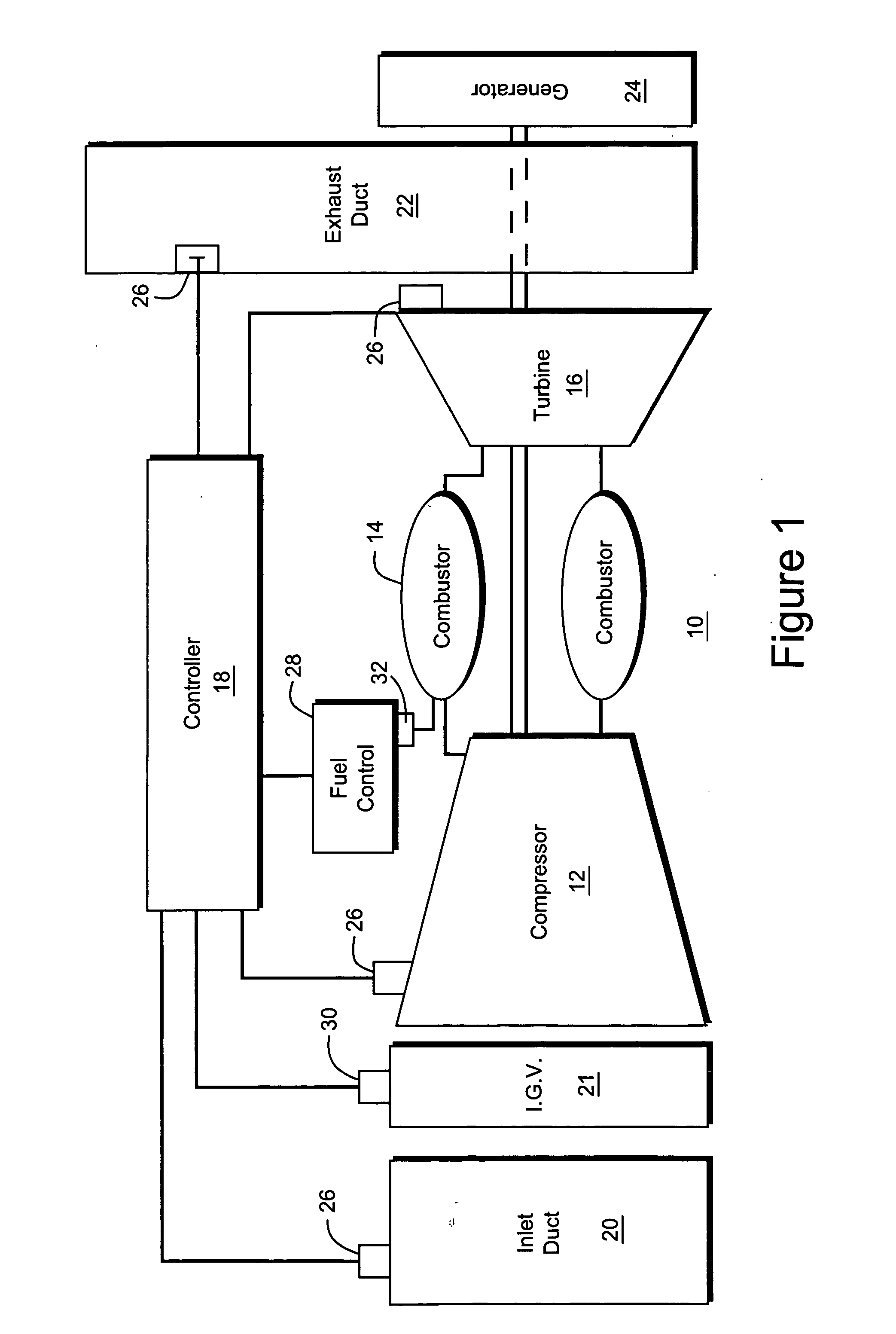
[0014] Part load operation of a gas turbine often involves a control system adjusting a total fuel flow to achieve the part-load level and adjusting the compressor inlet guide vane (IGVs) to set the gas turbine cycle match point for the desired part-load level. Further, the controller schedules the fuel splits for the combustor to maintain the desired combustion mode, e.g., part-load total fuel flow, and operate the gas turbine within established operability boundaries, such ...


PUM


Abstract

A method for determining a target exhaust temperature for a gas turbine including: determining a target exhaust temperature based on a compressor pressure condition; determining a temperature adjustment to the target exhaust temperature based on at least one parameter of a group of parameters consisting of specific humidity, compressor inlet pressure loss and turbine exhaust back pressure; and adjusting the target exhaust temperature by applying the temperature adjustment.

Description

BACKGROUND OF THE INVENTION [0001] The present invention relates generally to controllers for a combustion system for a gas turbine. In particular, the invention relates to a combustor control algorithm for fuel splits and nitrogen oxide / nitrogen dioxide (NOx) leveling. [0002] Industrial and power generation gas turbines have control systems (“controllers”) that monitor and control their operation. These controllers govern the combustion system of the gas turbine. Dry Low NOx (DLN) combustion systems are designed to minimize emissions of NOx from gas turbines. The controller executes an algorithm to ensure safe and efficient operation of the DLN combustion system. Conventional DLN algorithms receive as inputs measurements of the actual exhaust temperature of the turbine and the actual operating compressor pressure ratio. DLN combustion systems typically rely on the measured turbine exhaust temperature and compressor pressure ratio to set the gas turbine operating condition, e.g., de...

Claims


Application Information

Patent Timeline
Patent Type & Authority Applications(United States)
IPC IPC(8): F02C9/00F02C9/28F23N1/00F23R3/34
CPCF02C9/28F05D2270/08F23N1/002F23N2023/08F23N2025/06Y10T477/40F23N2025/26F23N2041/20F23R3/34F05D2270/112F05D2270/303F23N2025/21F23N2225/06F23N2225/26F23N2225/21F23N2223/08F23N2241/20
Inventor HEALY, TIMOTHY ANDREWSIMONS, DERRICK WALTER
Owner GENERAL ELECTRIC CO
Why Eureka
Try Eureka