
Bearing unit for wheel and method of manufacturing the same

a technology of bearing unit and bearing body, which is applied in the direction of bearing unit rigid support, manufacturing tools, transportation and packaging, etc., can solve the problems of difficult to obtain perfect perpendicularity, high cost, and judder followed by unpleasant noises, so as to prevent the generation of judder at braking operation, the effect of checking the deflection of the rotor of the braking uni

Inactive Publication Date: 2005-06-02
NSK LTD
View PDF5 Cites 15 Cited by
  • Summary
  • Abstract
  • Description
  • Claims
  • Application Information

AI Technical Summary

Benefits of technology

[0021] According to the wheel bearing unit of the invention composed as mentioned above and the manufacturing method thereof, it is possible to eliminate influences causing the deformation in the mounting surface of the mounting flange accompanied with press-fitting to fix the base portions of the studs into the mounting holes formed in the mounting flange.
[0023] Further, according to the wheel bearing unit and the manufacturing method thereof described in the second and third aspects of the invention, by press-fitting the base portion of the stud into the mounting hole, although the surface precision in the mounting surface of the mounting flange is deteriorated, since deteriorated parts are cut out by a subsequent processing, influences by the deterioration in the surface precision by the press-fitting insertion can be eliminated.
[0024] As a result, it is possible to check deflection of the braking rotary body fixed to the mounting flange and prevent generation of the judder caused at braking operation.

Problems solved by technology

It is known that vibrations called as a judder followed by unpleasant noises often occur when braking the automobile.
It is, however, difficult to obtain a perfect perpendicularity due to an unavoidable manufacturing error.
However, since the prior art disclosed in this publication precisely finishes a surface which is not originally needed as a reference surface, not only a cost increases, but also no consideration is taken for applying a heat treatment to the respective components.
Therefore, an error, etc. between the end surface of each inner ring and each inner ring raceway is included as an error of the parallelism between the mounting surface of the mounting flange and the inner ring raceway.
Further, since the contact portion between the hub and the inner ring is not processed based on the mounting surface of the mounting flange, it is difficult to sufficiently increase the parallelism between the mounting surface and the inner ring raceway.
However, in a case of the former, the selecting operation for combination is troublesome, and in a case of the latter, the mechanical apparatus for processing is complicated and becomes large in size, resulting in an increase in cost in both cases.
In such a conventional structure, the deformation of the mounting surface accompanied with press-fitting the stud into the mounting flange is simply considered, and the effect cannot be expected so much.
In contrast, in case the width of the serration part is reduced for increasing the distance, it becomes difficult to surely prevent the stud from being turned.

Method used


Image

  • Bearing unit for wheel and method of manufacturing the same
  • Bearing unit for wheel and method of manufacturing the same
  • Bearing unit for wheel and method of manufacturing the same

Examples


first embodiment

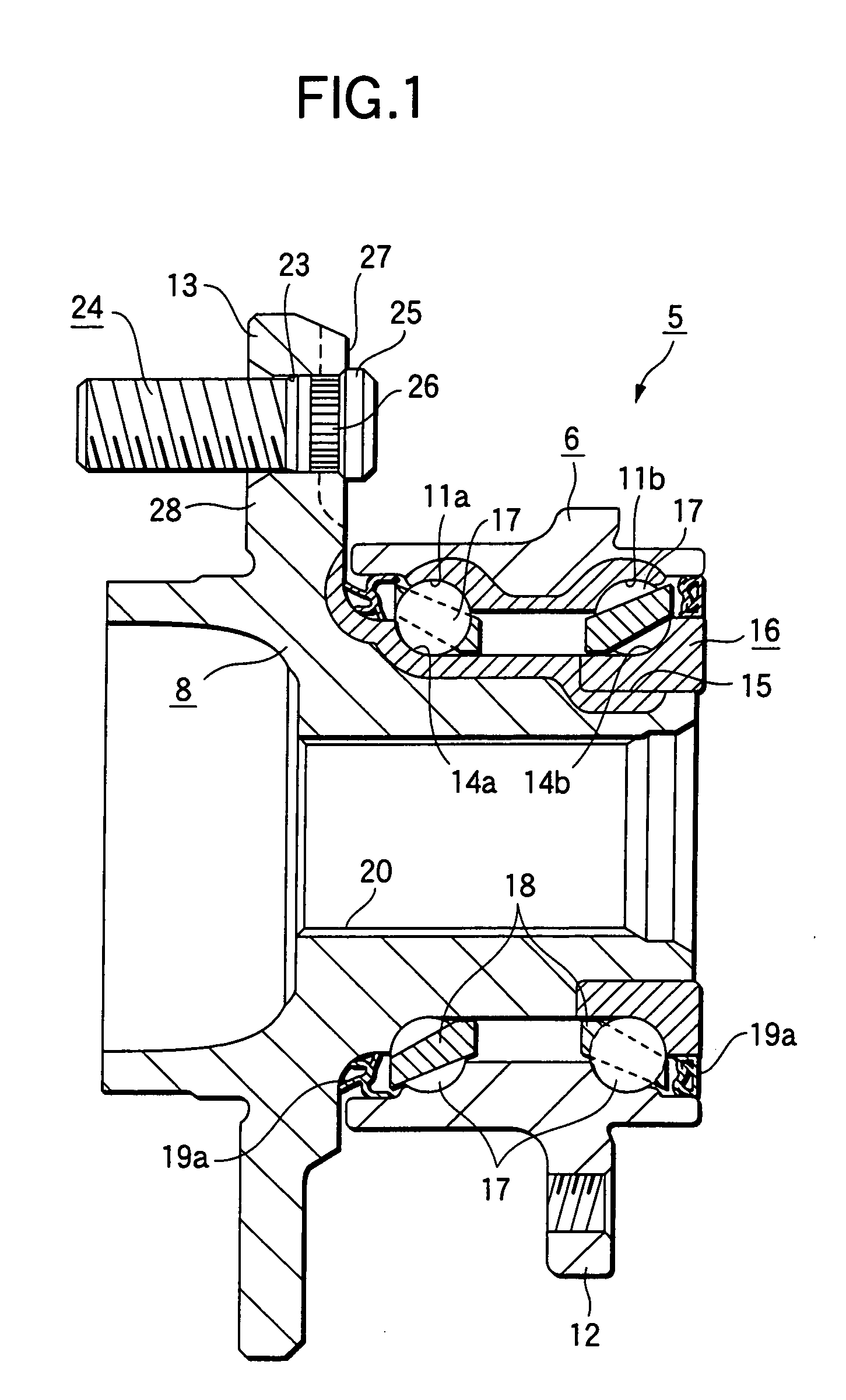
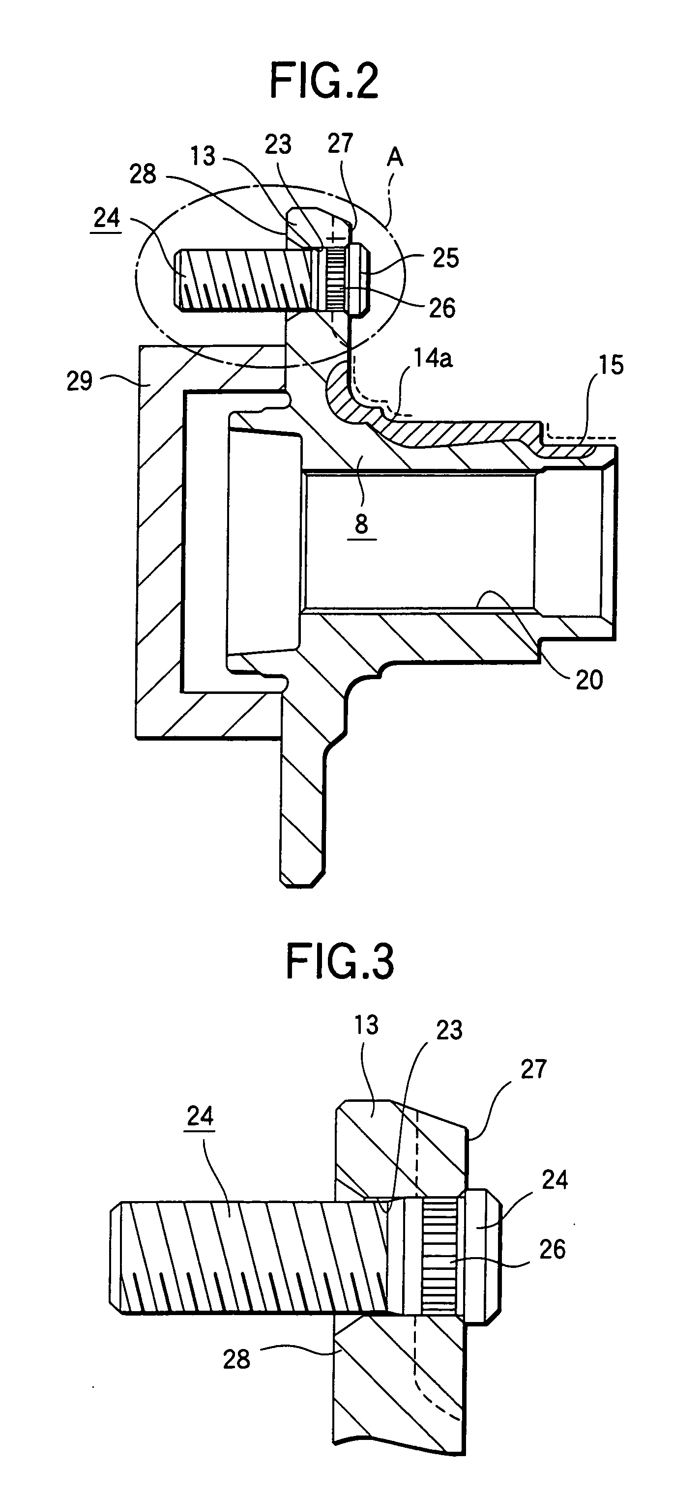
[0033]FIGS. 1 through 3 show the invention.

[0034] At the outer peripheral surface of the outer ring 6 which is the stationary ring, there is provided a joint flange 12 for fixedly connecting the outer ring 6 to the knuckle 3 (FIG. 8). At the inner peripheral surface of the outer ring 6 which is a stationary-side peripheral surface, there are formed the outer ring double raceways 11a, 11b which are respectively the stationary-side raceway surfaces. A portion, indicated by the lattice-hatching in an upper half part of FIG. 1, which is at the inner peripheral surface of an intermediate portion the outer ring 6, including these outer ring raceways 11a, 11b, is hardened over its entire periphery by a high-frequency hardening.

[0035] Of the outer peripheral surfaces of the hub 8 and the inner ring 16 corresponding to the rotary rings, areas facing to the outer bearings 11a, 11b respectively, there are provided the inner ring raceways 14a, 14b corresponding to the rotary side-raceway surfa...


PUM


Abstract

At a surface opposite to a mounting surface 28 at a part of the mounting flange 13, a projecting part 27 is provided so as to surround the opening part of the mounting holes 23 for press-fitting each stud thereinto. A finishing process of the mounting surface 28 is carried out after the stud 24 is press-fitted into the mounting hole 23.

Description

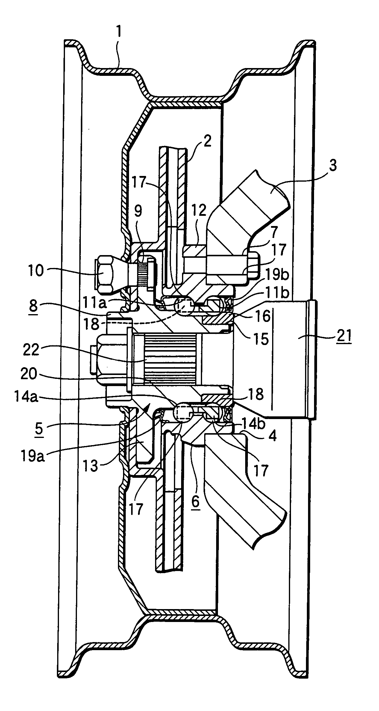
BACKGROUND OF THE INVENTION [0001] 1. Field of the Invention [0002] The present invention relates to an improvement of a bearing unit for wheel for supporting a wheel of an automobile as well as a rotary body for braking such as a rotor or a drum, and to an improvement of a method of manufacturing such a bearing unit for wheel. [0003] 2. Description of the Related Art [0004] A wheel 1 constituting a traveling wheel of an automobile and a rotor 2 constituting a disc brake as a braking apparatus are rotatably supported by a knuckle 3 which constitutes a suspending apparatus with a structure, for example, as shown in FIG. 8. To be specific, a circular supporting hole 4 is formed in the knuckle 3. An outer ring 6 being a stationary ring constituting a bearing unit 5 for the wheel, to which the present invention is applied, is fixed to within the supporting hole 4 by use of a plurality of bolts 7. On the other hand, the wheel 1 and the rotor 2 are fixedly connected to a hub 8 as a compon...

Claims


Application Information

Patent Timeline
IPC IPC(8): B60B27/00F16C19/18
CPCB60B3/04B60B27/00B60B27/0005B60B27/0026B60B27/0094Y10T29/497Y10T29/49535Y10T29/49536Y10T29/49945Y10T29/49533Y10T29/49696F16C19/186F16C2326/02F16C35/06
Inventor KANEKO, TAKEYASU
Owner NSK LTD
Learn More