

Valuable document
a document and value technology, applied in the field of data carriers, to achieve the effect of increasing design freedom and considerable economic advantages
- Summary
- Abstract
- Description
- Claims
- Application Information
AI Technical Summary
Benefits of technology
Problems solved by technology
Method used
Image

Examples
example 1
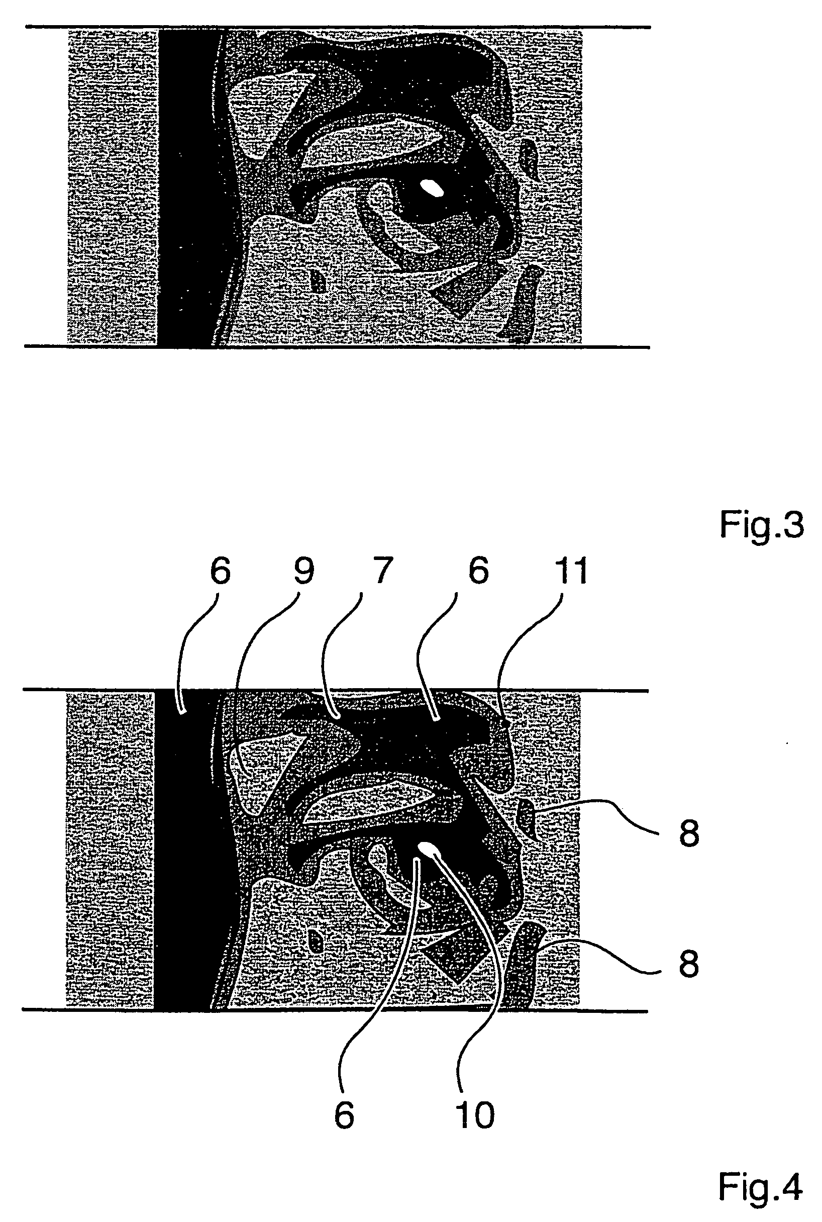
[0083] If a most realistic copy of the master is to be obtained, it is expedient to perform the screening as an areal resolution of the original image. This variant is shown in FIG. 4. Partial surfaces 6, 7, 8, 9 and 10 are thus obtained from the original itself. This means that the partial surfaces are based on a pictorial section in the original. This is effected automatically in the preparation of halftone separations whereby areas corresponding to a certain tonal-value range are assigned partial surfaces which are then rendered with a uniform tonal value. This leads to areally resolved originals in which the particular tonal values are subdivided into tonal-value ranges and each tonal-value range rendered by a defined tonal value. In the case of e.g. five tonal-value ranges, the total range of tonal values 0 to 100% is subdivided e.g. into five equal parts, i.e. from 1 to 20%, from 21 to 40%, from 41 to 60%, etc. Then each of the tonal-value ranges is rendered collectively by e....
example 2
[0085] Besides the method described in Example 1 of determining the partial surfaces in dependence on the picture motif, it is also possible to bring the original in congruence with a separately produced screen to produce the partial surfaces of the printed image. According to this embodiment, a screen is placed over the original image, i.e. the original is split into partial surfaces quite independently of the motif. Said partial surfaces, which correspond to the partial surfaces in the later inventive printed image, are assigned tonal values. The finer the screen, in other words, the smaller the partial surfaces constituting the inventive halftone image, the more image details can be rendered. Said tonal values are then converted into engraving depths for the printing plate, as described above.
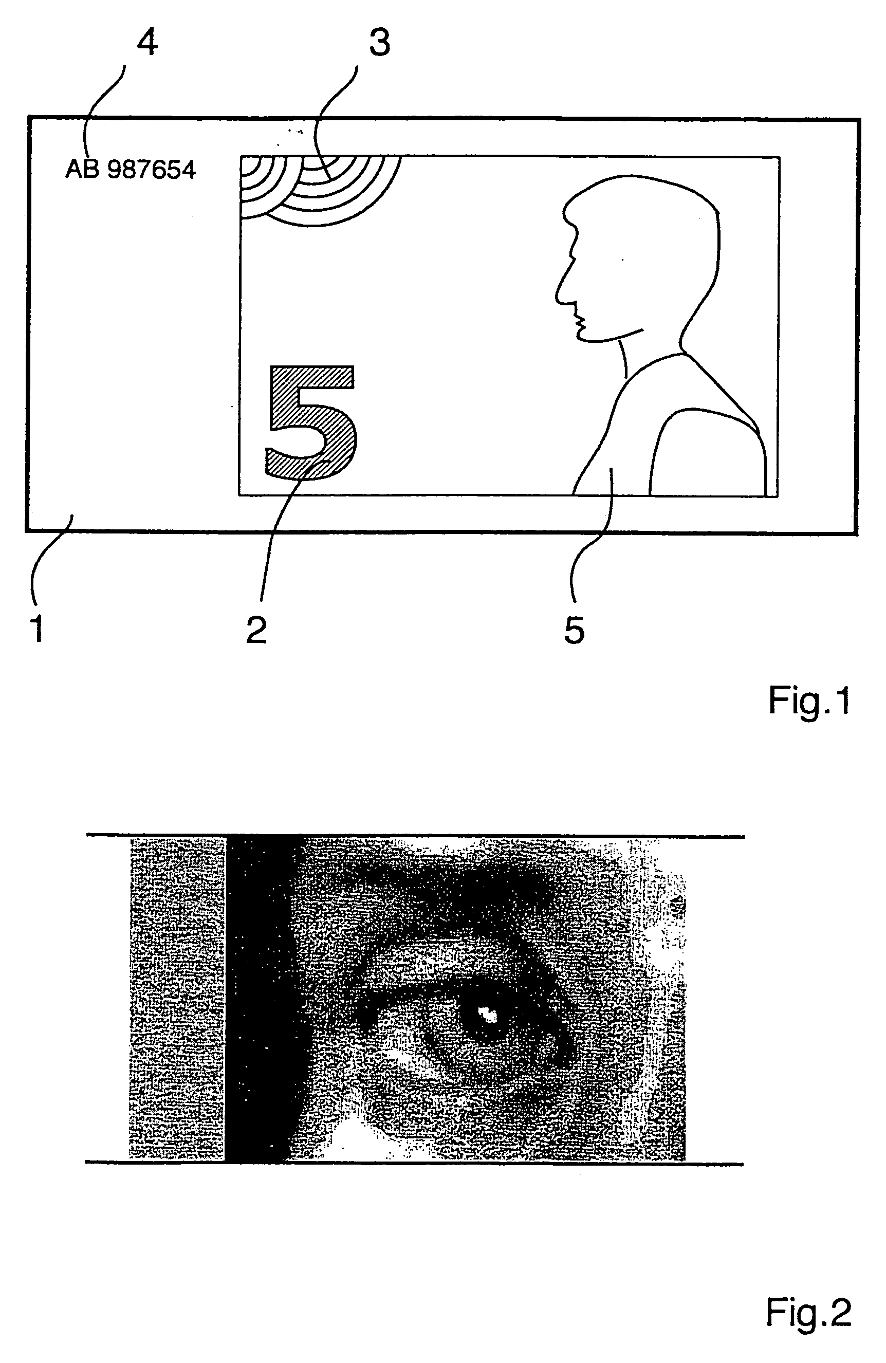
[0086] In the simplest case, a pixel screen is used. In FIG. 5, the original from FIG. 2 has been superimposed with such a screen. This causes the original to be resolved into uniform squar...
example 3
[0090] The example illustrated in FIG. 6, FIG. 6a and FIG. 6b is based, like Example 2, on the use of a pixel screen. The difference, however, is that not the classic halftone image from FIG. 2 is superimposed with the screen, but the halftone image from FIG. 3 constructed from halftone separations.
[0091] As in Example 2, each individual pixel is assigned a certain tonal value. Since the original is limited to five tonal values, the image converted into pixels also has only five tonal values, as shown in FIG. 6a. That is, the image is constructed here from a defined number of tonal values and according engraving depths.
[0092]FIG. 6 shows the halftone image from five tonal-value separations superimposed with the pixel screen. FIG. 6a shows detail “x” indicated in FIG. 6 wherein tonal values have already been assigned to the pixels. FIG. 6b shows the printed image associated with FIG. 6a, one pixel corresponding to one partial surface 12.
[0093] The remarks under Example 2 apply ana...
PUM
 Abstract
Description
Claims
Application Information