Solar cell module edge face sealing member and solar cell module employing same

a solar cell module and sealing member technology, applied in photovoltaic supports, pv power plants, solid-state devices, etc., can solve the problems of increased work operations, difficult to achieve uniform sealing, watertightness, etc., to improve the ease of operation and improve the sealing

Inactive Publication Date: 2005-06-02
SHARP KK
View PDF5 Cites 82 Cited by
  • Summary
  • Abstract
  • Description
  • Claims
  • Application Information

AI Technical Summary

Benefits of technology

[0028] As described above, one or more embodiments of the present invention is/are predicated upon a situation in which the solar cell module construction is such that the solar cell module body or bodies is/are captured within the frame body or bodies. In addition, a structure may be adopted such that the edge face sealing member(s), of two-layer construction and being frame-like in shape and formed in more or less parallel fashion with respect to outer shape(s) of the solar cell module body or bodies and/or being formed in such shape as to more or less conform to respective sides of the solar cell module body or bodies, is or are prepared; such edge face sealing member(s) being captured within the frame body or bodies so as to be captured thereby along substantially entire edge portion perimeter(s) of the solar cell module body or bodies. Because a construction is thus adopted in which the frame-shaped, integral-type edge face sealing member(s) and/or the edge face sealing member(s) of such shape as to more or less conform to respective sides of the solar cell module body or bodies is/are captured along substantially entire edge portion perimeter(s) of the solar cell module body or bodies, intimate contact and definitive sealing is permitted, permitting definitive prevention of entry by water, even where the solar cell module body or bodies is/are such that the light-receiving glass body or bodies is/are nonflat and/or nonsmooth on the light-receiving side thereof.
[0029] Furthermore, because the edge face sealing member(s) which is or are c-shaped and/or u-shaped in cross-section is or are made to capture the solar cell module body or bodies, and while in this state, these are then caused to be captured by the f...

Problems solved by technology

However, with the waterproofing structure of the foregoing Patent Reference No. 1, there has been the problem that because the structure is such that, simultaneous with capturing of the outside perimeter edge portion of solar cell module body 4 within groove 54e of frame body 5, tape-like waterproofing member 61 is progressively captured within groove 54e of frame body 5 as it is pressed thereinto, notwithstanding the fact that one of the rim portions of waterproofing member 61 may in fact have been made to adhere to the tip portion of flange 54f, the pressure of insertion can nonetheless cause waterproofing member 61 to slip, making it difficult to achieve a seal which is uniform along the entire perimeter edge portion of solar cell module body 4.
Furthermore, there has been the problem that because the portion that has slipped and extends outside of the groove of the frame body necessitates postprocessing in which a worker uses a knife or the like to remove it, this has increased...

Method used


Image

  • Solar cell module edge face sealing member and solar cell module employing same
  • Solar cell module edge face sealing member and solar cell module employing same
  • Solar cell module edge face sealing member and solar cell module employing same

Examples


first embodiment

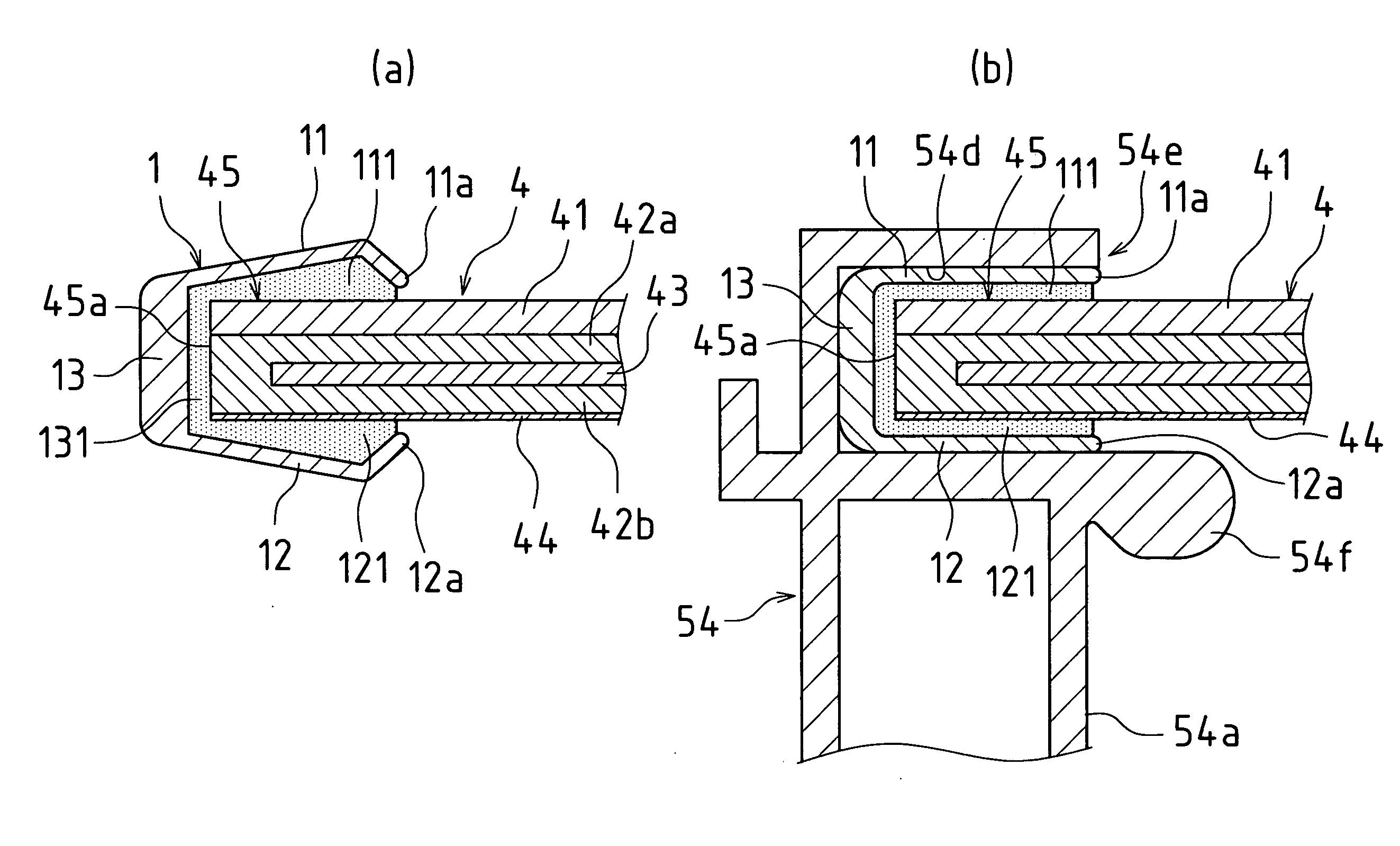
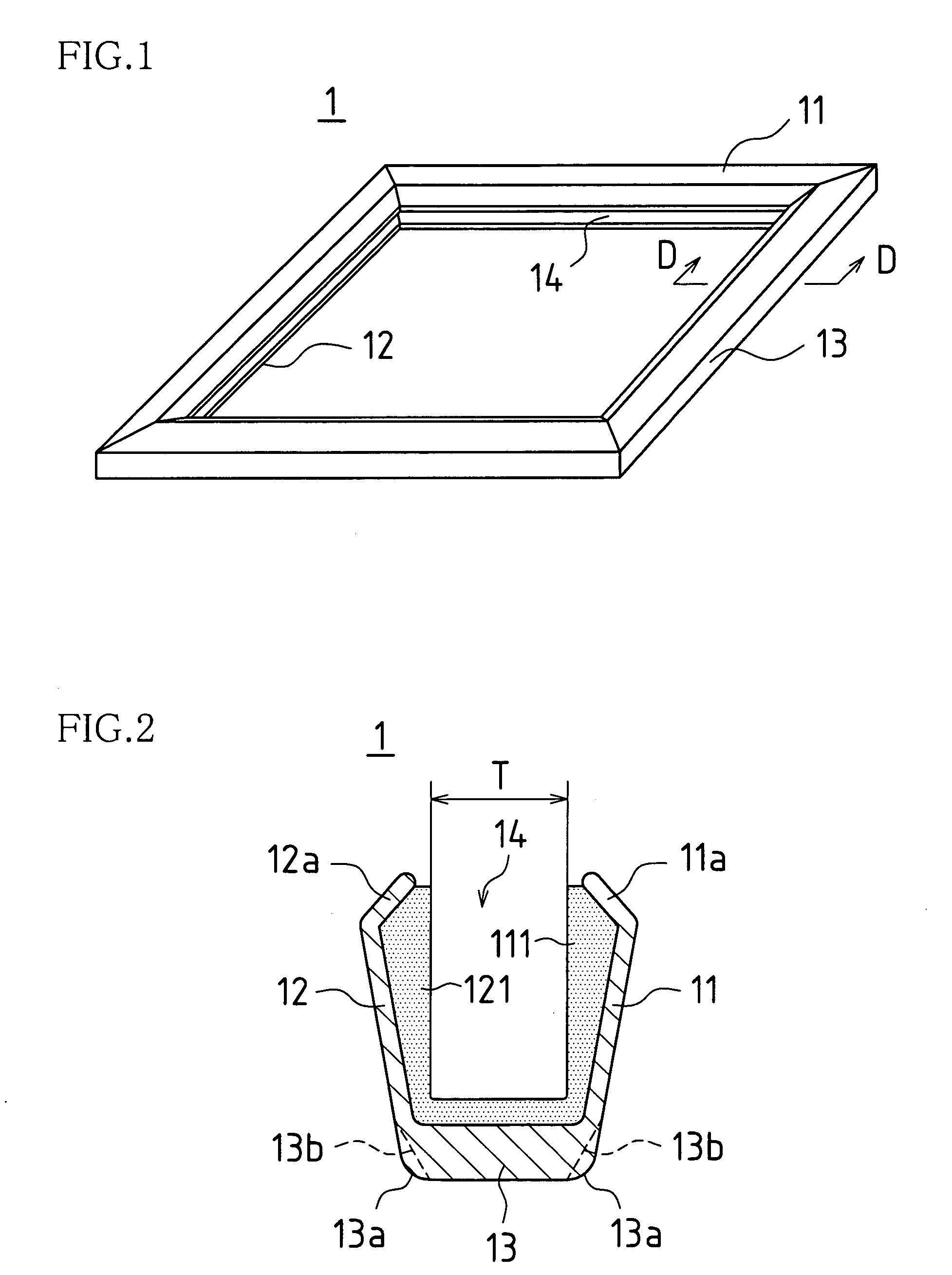
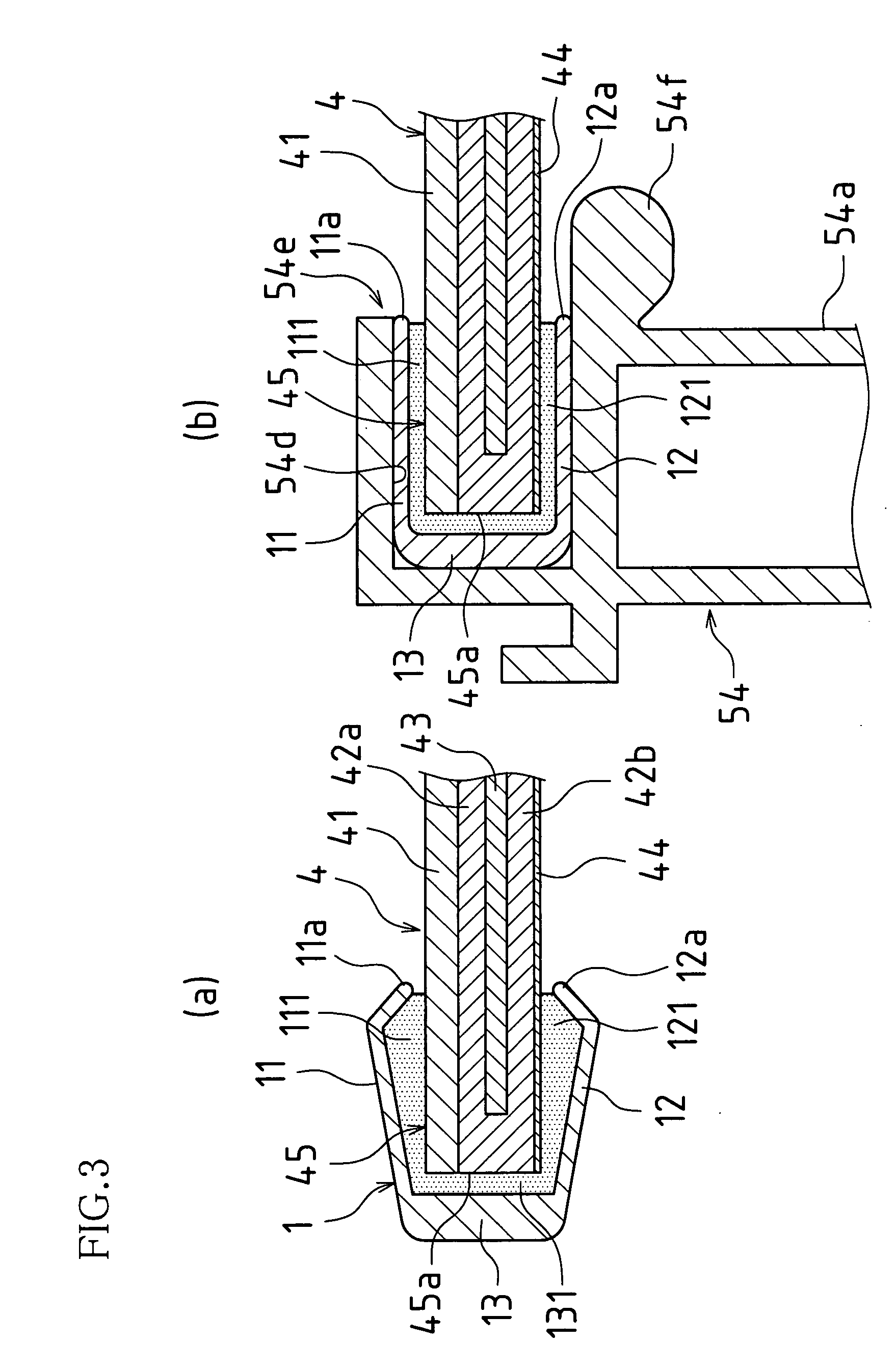
[0046] [FIG. 1 is an oblique view of the entirety of an edge face sealing member 1 associated with a first embodiment of the present invention, and FIG. 2 is a cross-sectional view of section D-D in FIG. 1. Note that, in the present first embodiment, the description below is carried out in terms of a solar cell module body employing superstrate structure such as that of solar cell module body 4 shown in FIG. 10, and in terms of a frame body employing structure such as that of frame body 5 shown in FIG. 12.

[0047] This edge face sealing member 1, which is frame-like in shape and is formed in more or less parallel fashion with respect to the outer shape of solar cell module body 4 shown in FIG. 10, is captured by frames 51, 52, 53, and 54 of frame body 5 shown in FIG. 9 so as to be captured thereby along substantially the entire perimeter of edge portion 45 (see FIG. 10) of solar cell module body 4.

[0048] As shown in FIG. 2, this edge face sealing member 1 is roughly c-shaped in cros...

second embodiment

[0054]FIG. 4 is a sectional view of edge face sealing member 1A associated with a second embodiment of the present invention.

[0055] Edge face sealing member 1A of the present second embodiment differs from edge face sealing member 1 of the foregoing first embodiment in that lower sealing region 12A abutting weather-resistant back-surface sealing film 44 of solar cell module body 4 is formed so as to be longer than upper sealing region 11 abutting light-receiving glass surface 41 of solar cell module body 4, the constitution thereof being in other respects similar to that of edge face sealing member 1 of the foregoing first embodiment. Accordingly, where components are identical to those at edge face sealing member 1 of the first embodiment, identical reference numerals will be used and detailed description thereof will be omitted.

[0056] The reason for thus forming lower sealing region 12A such that it is longer than upper sealing region 11 is that, as shown in FIG. 12, flange 54f ...

third embodiment

[0060]FIG. 6 is a sectional view of edge face sealing member 1B associated with a third embodiment of the present invention.

[0061] Edge face sealing member 1B of the present third embodiment differs from edge face sealing member 1 of the foregoing first embodiment in that projections 11b and 12b are respectively formed on facing surfaces of upper sealing region 11 and lower sealing region 12, the constitution thereof being in other respects similar to that of edge face sealing member 1 of the foregoing first embodiment. Accordingly, where components are identical to those at edge face sealing member 1 of the first embodiment, identical reference numerals will be used and detailed description thereof will be omitted.

[0062] These projections 11b, 12b may take the form of single-rib and / or multiple-rib regions (two ribs being formed in the present third embodiment) formed in more or less parallel fashion with respect to perimeter edge portions (sides) of solar cell module body 4, i.e...


PUM


Abstract

Edge face sealing member(s) may be roughly c-shaped in cross-section, may be frame-like in shape and formed in more or less parallel fashion with respect to outer shape(s) of solar cell module body or bodies, may comprise upper sealing region(s) abutting front surface(s) of solar cell module body or bodies, may further comprise lower sealing region(s) abutting back surface(s) of solar cell module body or bodies, and may further comprise side sealing region(s) abutting edge face(s) of solar cell module body or bodies. Furthermore, sealing region(s) may be roughly c-shaped in cross-section; may comprise upper sealing region(s) abutting front surface(s) of solar cell module body or bodies, lower sealing region(s) abutting back surface(s) of solar cell module body or bodies, and side sealing region(s) abutting edge face(s) of solar cell module body or bodies; may be of two-layer construction; and outer layer(s) may be hard, hardness(es) of inner layer(s) being less than that of outer layer(s); as a result of which there may be intimate contact even with nonflat and/or nonsmooth glass surface(s), permitting sealing.

Description

BACKGROUND OF INVENTION [0001] This application claims priority under 35 USC 119(a) to Patent Application No. 2003-399730 filed in Japan on 28 Nov. 2003 and to Patent Application No. 2004-40233 filed in Japan on 17 Feb. 2004, the content of both of which is incorporated herein by reference in its entirety. [0002] The present invention relates to an edge face sealing member for a solar cell module capable of being installed on roof portions of residential buildings or the like, and in particular, pertains to an improvement for ensuring watertightness between solar cell module body or bodies and frame body or bodies supporting same. [0003] As shown in FIG. 9, a solar cell module might typically comprise solar cell module body or bodies 4 and frame body or bodies 5. FIG. 9(a) is a plan view of solar cell module 2; FIG. 9(b) indicating the view from arrow B at FIG. 9(a), and FIG. 9(c) indicating the view from arrow C at FIG. 9(a). [0004] The integrally laminated superstrate construction...

Claims


Application Information

Patent Timeline
IPC IPC(8): H01L25/00H01L31/042H01L31/048
CPCH01L31/048H02S20/00Y02E10/50H02S30/10
Inventor YOSHIDA, HIROYUKIFUKUDA, YUKIOSUZUKI, YUJIUMEMOTO, AKIMASA
Owner SHARP KK
Why Eureka
Try Eureka