Damping valve assembly with a progressive damping force characteristic

a technology of damping force and damping valve, which is applied in the direction of shock absorbers, mechanical equipment, transportation and packaging, etc., can solve the problems of real stroke loss and the need to accept a considerable increase in weight, and achieve the effect of simple control slide components, no sacrifice of comfort, and increased damping for

Inactive Publication Date: 2005-06-02
ZF FRIEDRICHSHAFEN AG
View PDF11 Cites 29 Cited by
  • Summary
  • Abstract
  • Description
  • Claims
  • Application Information

AI Technical Summary

Benefits of technology

[0010] The great advantage of the invention is that a conventional damping valve can be used as a basis, that is, a valve with a damping force characteristic which is adjusted for normal driving conditions and which does justice to the claims of both comfort and safety. Through the use of the control slide, it is also possible to obtain, at high piston velocities, a damping force characteristic which is independent of the instantaneous level of the wheel and also independent of the range of the damping force characteristic provided to cover normal driving conditions, with the result that there is no sacrifice of comfort under any conditions.
[0011] It is also provided that, with respect to the flow path of the damping medium, the control slide is installed in series with the damping valve. The inflow or outflow of damping medium is closed off at the damping valve in order to achieve an overall increase in the damping force.
[0012] In a further elaboration of the invention, the pressure actuated surface of the control slide is adjacent to a throttle point, which leads to the first damping valve assembly. Thus a space-saving design of the overall damping valve can be achieved.
[0013] Thus the throttle point is determined by the outside diameter of the control slide and possibly by an inside wall of the cylinder of the vibration damper. This arrangement allows the use of very simple control slide components, because in most cases the cylinder is already manufactured as a precision component.
[0014] To ensure that the control slide operates in a defined manner, it is held in the open position by a spring.
[0015] To protect not only the damping valve device itself but also the vibration damper in which the damping valve device is installed, the throttle point is connected in parallel to a pressure-limiting valve. As a result, it is possible to limit the achievable damping force of the damping valve to a defined value.

Problems solved by technology

What appears to be the simplest possibility at first glance is simply to reinforce the vehicle body in the endangered area, but this would make it necessary to accept a considerable increase in weight.
Another disadvantage of this principle is that the stop spring on the piston side causes a real loss of stroke.
Various problems occur in practice when the solution according to DE 31 07 517 A1 is used.

Method used


Image

  • Damping valve assembly with a progressive damping force characteristic
  • Damping valve assembly with a progressive damping force characteristic
  • Damping valve assembly with a progressive damping force characteristic

Examples


Embodiment Construction

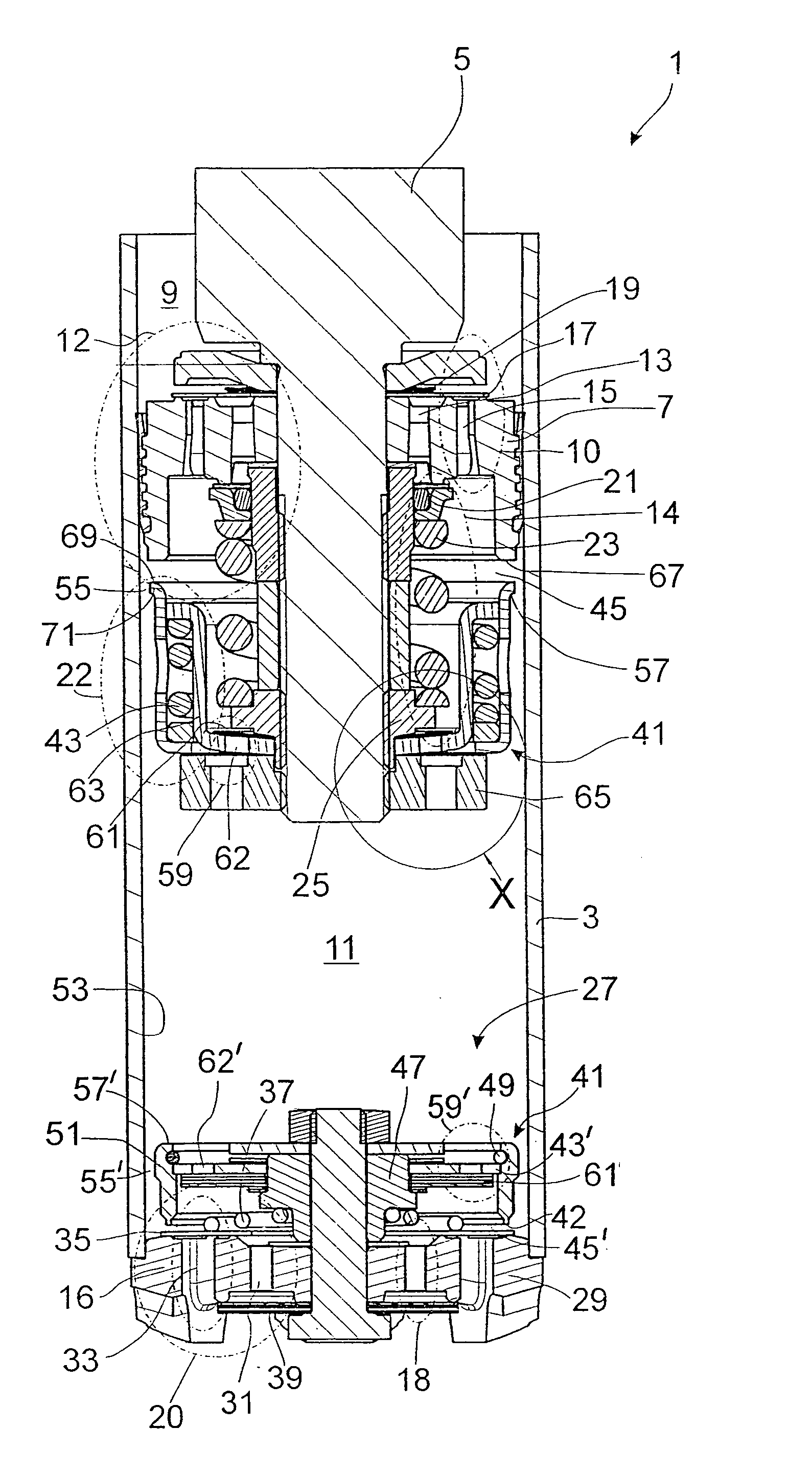
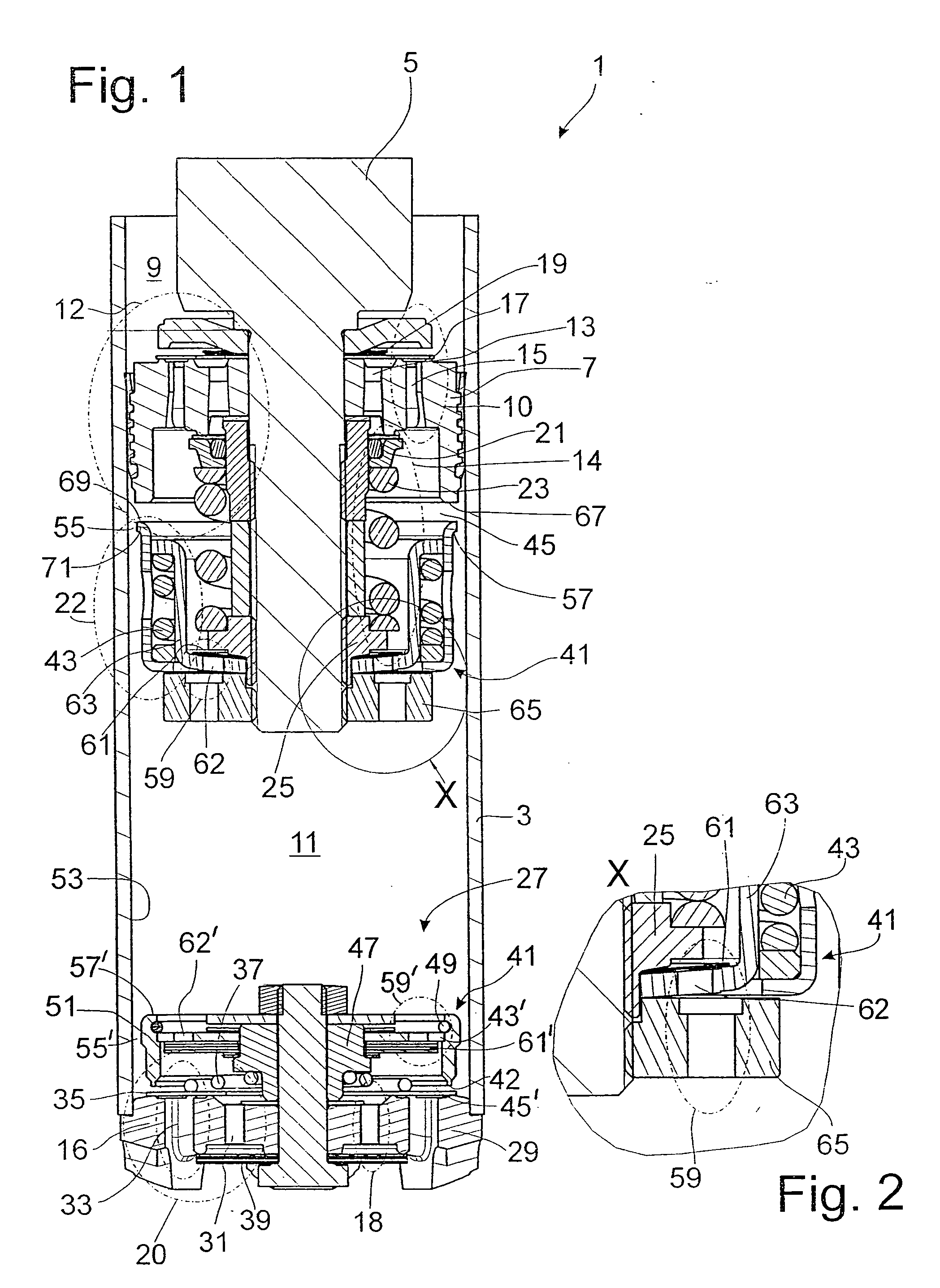
[0038]FIG. 1 shows a part of a vibration damper 1, in the damping medium-filled cylinder 3 of which a piston rod 5, to which a piston 7 is fastened, is guided with freedom of axial movement. The piston 7 divides the cylinder 3 into a working space 9 on the piston-rod side of the piston and a working space 11 on the side of the piston away from the piston rod. Groups of open channels 13, 15 are provided in the piston for the two flow directions of the damping medium. For the inward travel direction of the piston into the cylinder, the first assembly 10 of the damping valve 12 comprises the open channels 15, the outlet ends of which are at least partially covered on the top surface of the piston 7 by at least one valve disk 17 in conjunction with a valve spring 19. In the case of a vibration damper according to the single-tube principle, this first assembly—open channels 15, valve disk 17, and valve spring 19—would determine the damping force characteristic for normal driving conditio...


PUM


Abstract

Damping valve assembly includes a first damping valve, which, in a first operating range, opens as the flow velocity of the damping medium increases, where a second operating range with a progressive damping force characteristic is influenced by a throttle in conjunction with a control slide, which can be moved into a closed position. The control slide has a pressure-actuated surface, which, as a function of the flow velocity of the damping medium, acts in the closing direction on the control slide.

Description

BACKGROUND OF THE INVENTION [0001] 1. Field of the Invention [0002] The invention pertains to a damping valve assembly for a vibration damper having a piston which moves in a damping medium in a cylinder, the assembly including a first damping valve which, in a first operating range, opens as the flow velocity of the damping medium increases; and a first control slide which, in a second operating range with a progressive damping characteristic, can move in a closing direction to close a throttle. [0003] 2. Description of the Related Art [0004] DE 35 33 386 A1 describes a two-tube vibration damper, the piston of which carries a compression spring. The spring moves a control slide on a bottom valve into a closed position as a function of the stroke of the piston to produce a progressive damping force characteristic shortly before the end of the stroke. In a vehicle being driven at comparatively high speed over a section of bad road, it is possible for a wheel to move inward very abrup...

Claims


Application Information

Patent Timeline
Patent Type & Authority Applications(United States)
IPC IPC(8): F16F9/348F16F9/512
CPCF16F9/512F16F9/3485Y10T137/86509
Inventor FORSTER, ANDREAS
Owner ZF FRIEDRICHSHAFEN AG
Why Eureka
Try Eureka