Frame kit and methods therefor

a technology of frame kits and components, applied in the field of frame kits, can solve the problems of high cost of such enclosures, difficult modification of such enclosures by consumers, and high cost of shipping such enclosures

Inactive Publication Date: 2005-06-02
STAR CASE MFG CO +1
View PDF25 Cites 7 Cited by
  • Summary
  • Abstract
  • Description
  • Claims
  • Application Information

AI Technical Summary

Benefits of technology

[0008] It is a still further object of this disclosure to provide a plurality of improved corner members, a plurality of rail members and a plurality of fasteners in a kit form for simple construction of a variety of enclosures.

Problems solved by technology

Consequently, costs for such enclosures were relatively high, and in an after-market sense, modification of such enclosures by consumers was difficult to achieve.
Additionally the cost of shipping such enclosures was high because of the size of such enclosures.
Subsequently, certain knock-down components were offered in the market, which required tedious construction and specialized hardware and tools for constructing the knock-down components into a full enclosure.
Amongst limitations that exist for such knock-down components are: standardization in sizes, custom ordering for non-standard sized enclosures, assortment of parts needed for construction of the enclosure, time to construct the enclosure and strength considerations of the components and final enclosure.

Method used


Image

  • Frame kit and methods therefor
  • Frame kit and methods therefor
  • Frame kit and methods therefor

Examples


second embodiment

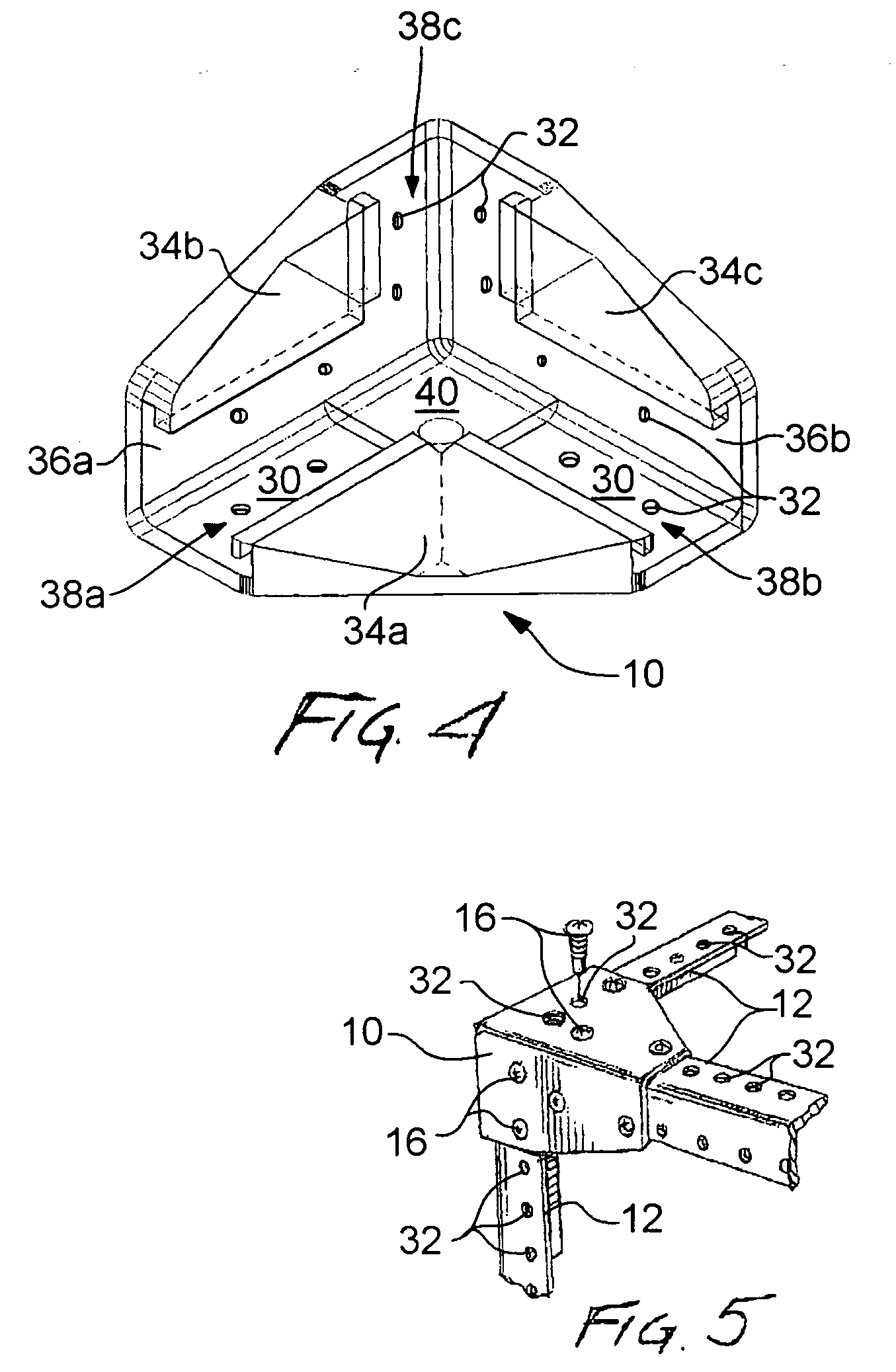
[0012] In accordance with this invention, a method for assembling a frame kit is disclosed. The method for assembling a frame kit comprises the steps of providing a plurality of rail members, each one of the rail members having a plurality of holes and providing a plurality of corner connectors, each one of the plurality of corner connectors including a base member having a plurality of holes and a reinforcing rib coupled to the base member, a pair of leg members, each having a plurality of holes, each one of the pair of leg members including a reinforcing rib coupled to each one of the pair of leg members, a first leg member of the pair of leg members substantially perpendicular to a second leg member of the pair of leg members, each one of the pair of leg members substantially perpendicular to the base member, a portion of the base member and a portion of the first leg member of the pair of leg members having a first inner slot, a portion of the base member and a portion of the se...

third embodiment

[0013] In accordance with this invention, a method for constructing a frame assembly from a frame kit is disclosed. The method comprises the steps of providing the frame kit comprising a plurality of rail members, each one of the rail members having a plurality of holes and providing the frame kit further comprising a plurality of corner connectors, each one of the plurality of corner connectors including a base member having a plurality of holes and a reinforcing rib coupled to the base member, a pair of leg members, each having a plurality of holes, each one of the pair of leg members including a reinforcing rib coupled to each one of the pair of leg members, a first leg member of the pair of leg members substantially perpendicular to a second leg member of the pair of leg members, each one of the pair of leg members substantially perpendicular to the base member, a portion of the base member and a portion of the first leg member of the pair of leg members having a first inner slo...

first embodiment

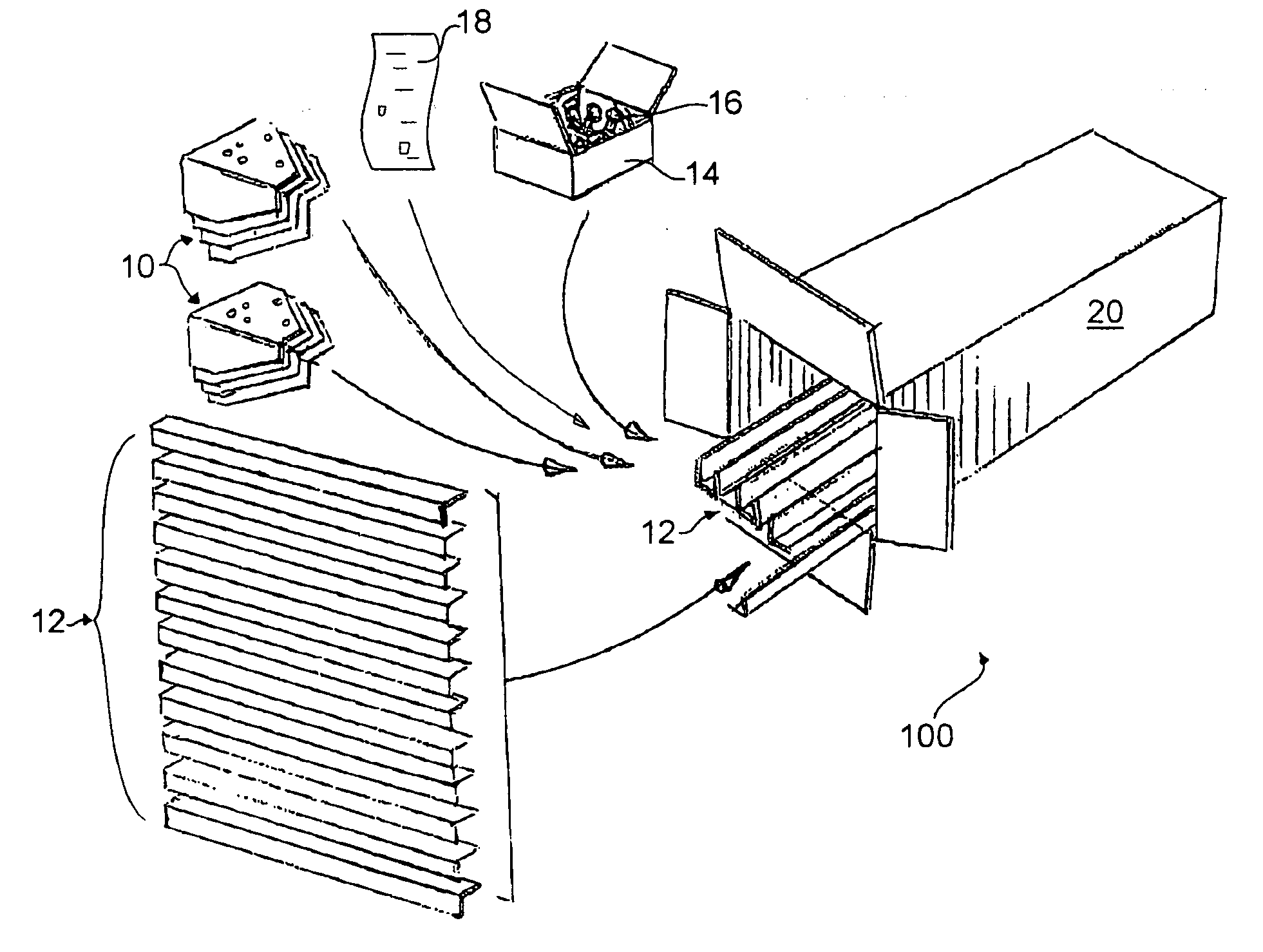
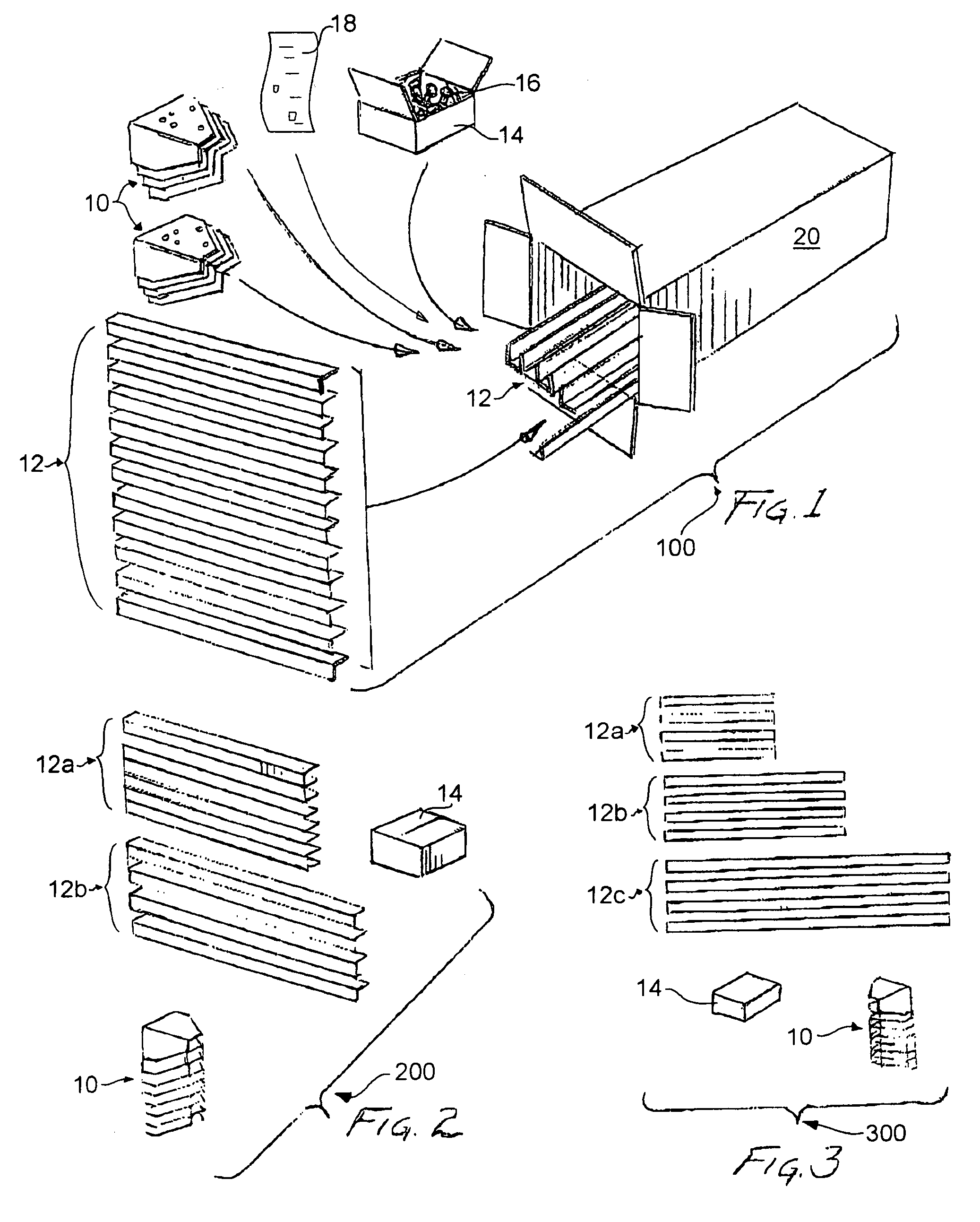
[0015]FIG. 1 is a perspective view of a frame kit comprising a plurality of corner connectors, a plurality of rail members having the same length, a first container including a plurality of fasteners, a set of instructions and a second container, with each one of the plurality of corner connectors, the plurality of rail members, the first container including the plurality of fasteners and the set of instructions being located in the second container according to the present invention.

[0016]FIG. 2 is a perspective view of a portion of a second embodiment of a frame kit comprising a plurality of corner connectors, a plurality of rail members with a first set of the plurality of rail members being of different length to a second set of the plurality of rail members and a first container including a plurality of fasteners (not shown) suitable for being located in the second container of FIG. 1 according to the present invention.

[0017]FIG. 3 is a perspective view of a portion of a third...


PUM


Abstract

A frame kit comprises a plurality of improved corner connectors and a plurality of rail members both having a plurality of holes, a plurality of fasteners for coupling each one of the corner connectors to one end of three rail members of the plurality of rail members and at least one set of instructions located in at least one container suitable for constructing at least one frame assembly. The frame kit may also comprise at least one of a plurality of leveling feet, a plurality of casters adapted for coupling to a portion of at least one of the corner connectors, a plurality of rib members for strengthening at least one frame assembly and a plurality of accessory members adapted to couple to at least one of the plurality of rail members. A method for assembling the frame kit and constructing at least one frame assembly is also disclosed.

Description

CROSS-REFERENCE TO RELATED APPLICATION [0001] This application is a Continuation in Part of U.S. application Ser. No. 10 / 361,403, filed Feb. 10, 2003 (published as U.S. Publication No. 2004 / 0155002 A1), entitled: Connecting Corner for Knock Down Racks in the name of the same Applicant.FIELD OF THE INVENTION [0002] This invention relates generally to frame kits and more specifically to a frame kit comprising at least a plurality of improved connecting corners, a plurality of rail members and a plurality of fasteners. BACKGROUND OF THE INVENTION [0003] Various manufacturers have provided equipment frame assemblies and equipment enclosures for storing electronic equipment. Most such enclosures and frame assemblies were supplied by these manufacturers in a fully assembled state and therefore required customization to comply with the needs of consumers. Consequently, costs for such enclosures were relatively high, and in an after-market sense, modification of such enclosures by consumers...

Claims


Application Information

Patent Timeline
Patent Type & Authority Applications(United States)
IPC IPC(8): F16B12/50H02B1/01
CPCH02B1/014F16B12/50
Inventor TOMA, DENNIS R.
Owner STAR CASE MFG CO
Why Eureka
Try Eureka