
Toilet roll holders

a roll holder and toilet technology, applied in the field of toilet roll holders, can solve the problems of inability to apply to roll holders that are already installed, typically more complex proposals, etc., and achieve the effect of facilitating access for insertion and increasing friction for

Inactive Publication Date: 2005-06-02
MOLLOY DAVID
View PDF5 Cites 4 Cited by
  • Summary
  • Abstract
  • Description
  • Claims
  • Application Information

AI Technical Summary

Benefits of technology

[0006] An aim of this invention is to provide apparatus for use with a toilet roll holder that resists unrolling of paper carried on the holder, yet which is simple and that, in some embodiments at least, can be fitted to existing toilet roll holders.
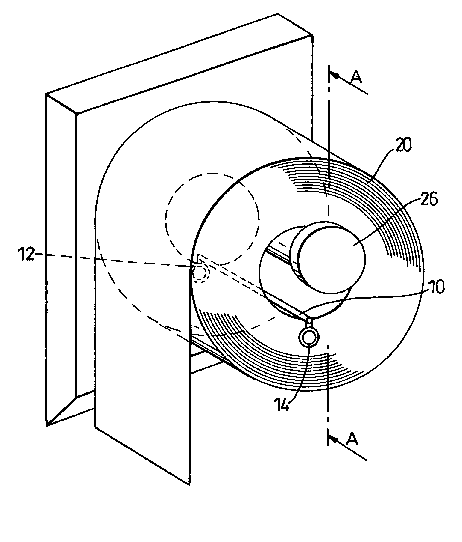
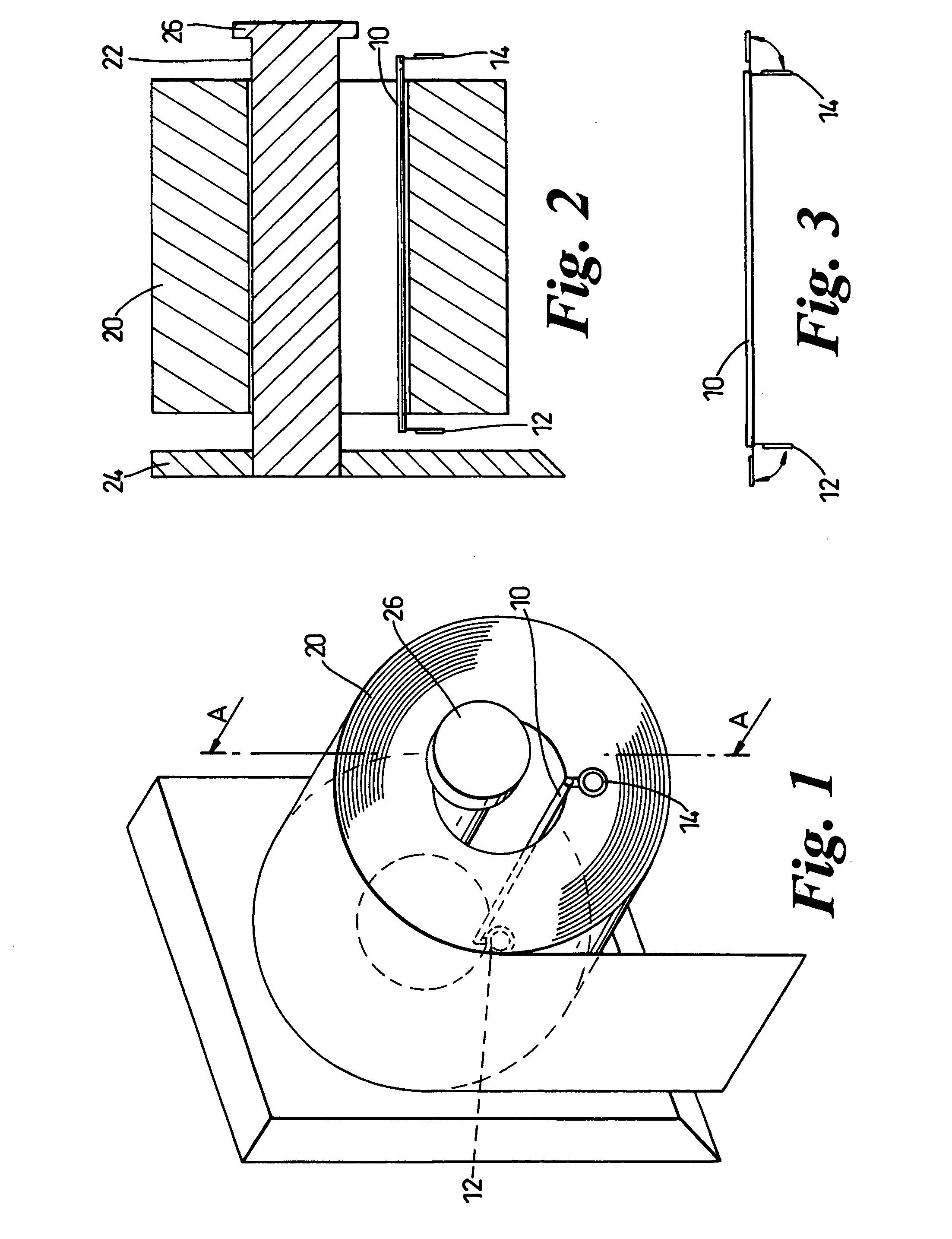
[0007] From a first aspect, this invention provides a stabilising bar assembly, to prevent inadvertent unwinding of a toilet roll mounted in a roll holder, the bar assembly being for insertion into the core of the toilet roll, the bar assembly including an elongate bar portion, there being finials at each of the opposite ends of the bar portion, the finials being articulate with respect to the bar portion, to allow the stabilising bar to be inserted into the core of the roll and resist the bar from rotating or slipping from the roll.
[0008] For use, the stabilising bar assembly is passed into the centre of the roll, such that it lies on the roll core. Its presence increases the friction force already present (due to its weight) and it also adds a second braking force that acts between the core or the roll and the stabilising bar itself. This second force is constant, irrespective to the weight of the roll.
[0009] The bar portion is preferably of such a length as to be slightly greater than the length of the roll core. In such embodiments, the finials hang down to opposite sides of the core when the apparatus is in use. This resists movement the bar out of the core and also prevents or resists it from rotating or slipping from the roll. This also eases access for insertion of the bar into the core of the roll. Since the ends of the stabilising bar will emerge from the roll, it is possible to add decoration, such as decorative motifs to the finials.

Problems solved by technology

However, these proposals have typically been considerably more complex than a conventional toilet roll holder, and they cannot be applied to roll holders that are already installed.

Method used


Image

  • Toilet roll holders
  • Toilet roll holders

Examples


Embodiment Construction

[0017] An embodiment of the invention will now be described in detail, by way of example, and with reference to the accompanying drawings.

[0018] With reference to the drawings, a stabilising bar assembly comprises a bar portion 10 and a pair of finials 12, 14

[0019] The bar potion 10 is formed as an elongate rod. This may be of metal, since it is advantageous that it has weight, but the metal selected is advantageously one that is resistant to corrosion. It may alternatively be formed of plastic or wood. Each finial 12, 14 is formed as a metal loop in this embodiment. In other embodiments, the finials might be formed from materials such as plastic or wood. Since the finials 12, 14 are visible, they can also be decorated to provide the apparatus with a favourable appearance.

[0020] Each of the finials 12, 14 is carried at a respective opposite end of the bar portion 10. The finials 12, 14 are free to articulate with respect to the bar portion 10, the axes of articulation being parall...


PUM


Abstract

A stabilising bar assembly, to prevent inadvertent unwinding of a toilet roll mounted in a roll holder is disclosed. The bar assembly is intended for insertion into the core of the toilet roll. The bar assembly includes an elongate bar portion, there being finials at each of the opposite ends of the bar portion, the finials being articulate with respect to the bar portion, to allow the stabilising bar to be inserted into the core of the roll and resist the bar from rotating or slipping from the roll. The axes of articulation are parallel, such that they can both hang down at opposite sides of a roll.

Description

BACKGROUND TO THE INVENTION [0001] 1. Field of the invention [0002] This invention relates to toilet roll holders. In particular, it relates to a toilet roll holder that resists the tendency for paper to run from the roll in a free and uncontrolled manner. [0003] Toilet rolls, when mounted in a roll holder, depend on friction between a bar of the roll holder and the core within the roll itself to prevent the weight of any unrolled, hanging, section of the roll from destabilising the roll, allowing it to unroll and deposit its contents on the floor. This friction force varies with the weight of the roll, so the friction force reduces as the roll becomes lighter as it is used. There tends to be a point at which the weight of the hanging section (which are dependent only on its length) may exceed the resistance of the friction force, particularly when combined with movement in the air around it. The friction force may then be overcome, causing the paper to unroll. [0004] 2. Summary of ...

Claims


Application Information

Patent Timeline
IPC IPC(8): A47K10/38
CPCA47K10/3836
Inventor MOLLOY, DAVID
Owner MOLLOY DAVID
Learn More