Method of moulding soles on shoe uppers, a shoe welt and a mould for carrying out the method

Active Publication Date: 2005-06-02
ECCO SKO
View PDF4 Cites 8 Cited by
  • Summary
  • Abstract
  • Description
  • Claims
  • Application Information

AI Technical Summary

Benefits of technology

[0016] Moreover according to the invention the support surface may be a face of a circumferential recess in the upper face of the lower mould part, in a cross-sectional view said face forming an angle v of 20-40°, preferably 25-35°, with the horizontal plane. As a result when moved into their closed position the upper mould and lower mould parts interact particularly effectively to tilt the welt about the radially innermost edge of the recess, whereby the welt is more

Problems solved by technology

The welt is arranged vertically and the sole material joining the welt and the shoe upper is thus visible between the shoe upper and the welt, which is not satisfactory.
The use of a two-part welt involves a risk of the sole mater

Method used


Image

  • Method of moulding soles on shoe uppers, a shoe welt and a mould for carrying out the method
  • Method of moulding soles on shoe uppers, a shoe welt and a mould for carrying out the method
  • Method of moulding soles on shoe uppers, a shoe welt and a mould for carrying out the method

Examples


second embodiment

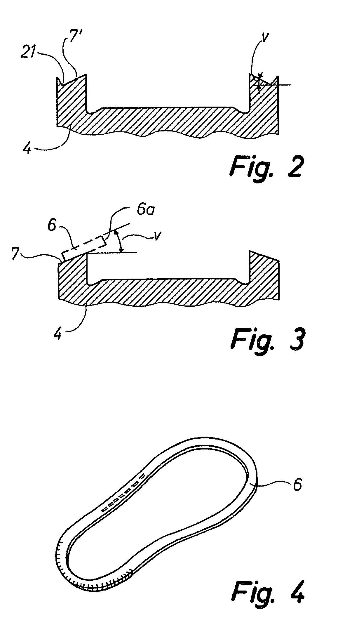
[0045]FIG. 9 is a sectional view of the welt according to the invention,

third embodiment

[0046]FIG. 10 is a sectional view of the welt according to the invention,

fourth embodiment

[0047]FIG. 11 is a sectional view of the welt according to the invention,

[0048]FIG. 12 shows a portion of the joint face of one of the upper mould halves, one branch of the Y-shaped supply conduit for the fluid sole moulding material being clearly visible, and

[0049]FIG. 13 shows a portion of the joint face of the other upper mould half, the other branch of the Y-shaped supply conduit being clearly visible.

BEST MODES FOR CARRYING OUT THE INVENTION

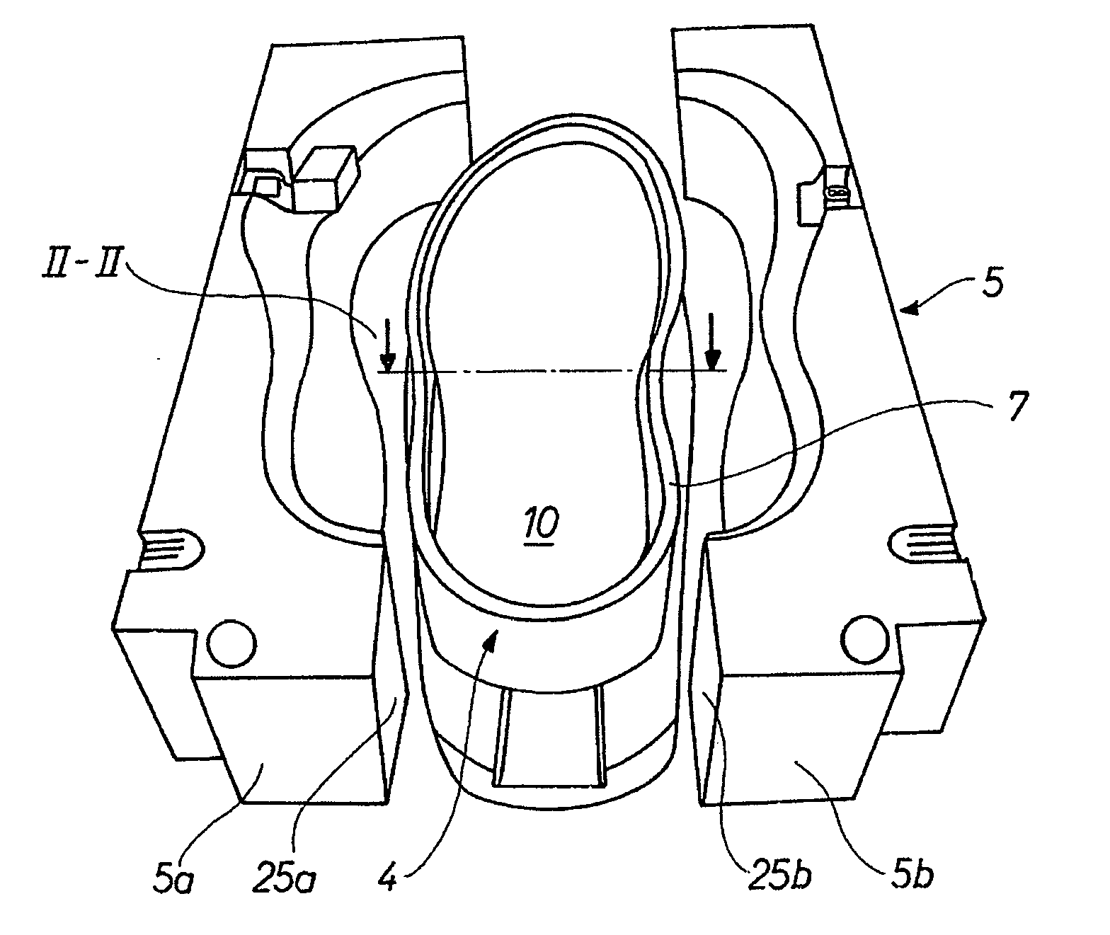
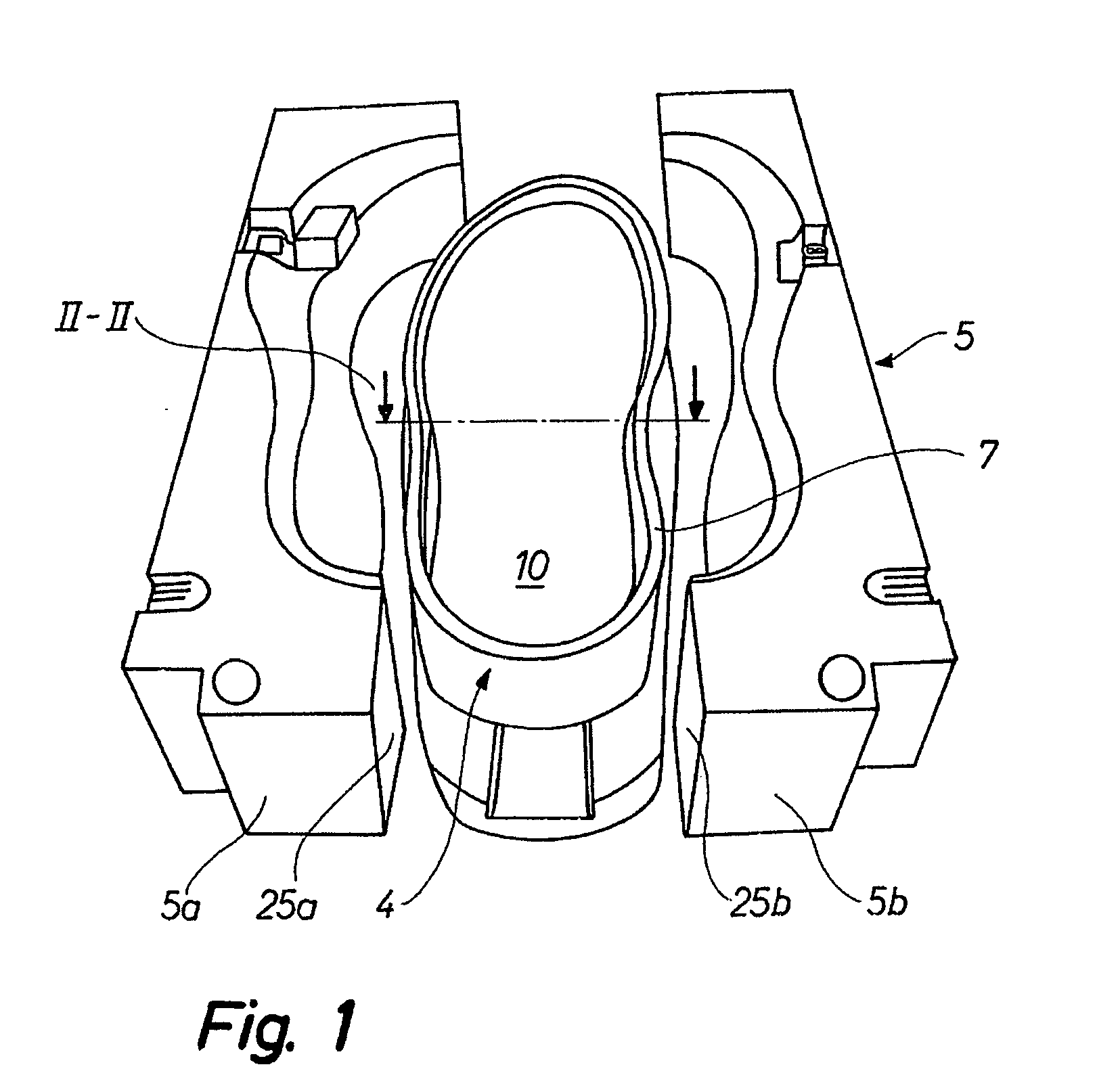
[0050]FIG. 1 illustrates a mould by means of which a method of moulding soles of a plastic material, eg. polyurethane, onto shoe uppers, may be carried out, a shoe upper 1 being arranged on a last 2, confer FIG. 5. As shown in FIG. 1 the mould 3 has a lower mould part 4 and an upper mould part 5 with two upper mould halves 5a, 5b. These upper mould halves may be moved to and fro each other in a horizontal plane. When the mould is used for the said method, the finished shoe will appear to have been actually welted. A welt 6 is used in the m...


PUM

PropertyMeasurementUnit
Lengthaaaaaaaaaa
Lengthaaaaaaaaaa
Fractionaaaaaaaaaa

Abstract

In a method of moulding a sole of a plastic material and a welt on a shoe upper (1) a mould (3) is used. The mould (3) includes at last (2), upon which a shoe upper (1) is arranged, an upper mould part (5) divided along a longitudinal middle plane and thus includes two halves (5a, 5b) being laterally movable in relation to the lower mould part (4) between an open and a closed mould position, and a lower mould part (4) being vertically movable in relation to the upper mould part (5) between an open and a closed mould position. For carrying out the method an annular shoe welt (6) is provided and arranged in the mould in the mould's open position. The two halves (5a, 5b) of the upper mould part (5) are closed and the lower mould part is moved into its closed position. As a result a circumferential support surface (7) on the upper face of the lower mould part (4) co-acts with a pressure surface (17) on the lower face of a projection (15) on each half (5a, 5b) of the upper mould part such that the portion of the welt (6) facing the shoe upper (1) it tilted inwards and downwards to bring the inner end face of the welt (6) into sealing engagement with the lower side section of the shoe upper (1). The shoe sole is then moulded in a manner known per se by supplying a plastic material to the cavity of the mould.

Description

TECHNICAL FIELD [0001] The invention relates to a method of moulding soles of a plastic material, eg polyurethane, and shoe welts on shoe uppers by means of a mould so as to provide the finished shoe with a welted appearance, said mould including a last, upon which a shoe upper is arranged, an upper mould part being divided along a longitudinal centre plane and thus including two halves being laterally movable in relation a lower mould part between an open and a closed mould position, and a lower mould part being vertically movable in relation to the upper mould part between an open and a closed mould position. BACKGROUND ART [0002] French publication No. 2609874 discloses a method of producing a shoe in which a welt is moulded onto the shoe to give the shoe the appearance of a welted shoe. The welt is arranged vertically and the sole material joining the welt and the shoe upper is thus visible between the shoe upper and the welt, which is not satisfactory. [0003] U.S. Pat. No. 3,85...

Claims


Application Information

Patent Timeline
IPC IPC(8): A43B15/00B29D35/00A43D86/00B29D35/10
CPCA43B9/04B29D35/061B29D35/06B29D35/00B29C39/10A43D25/00
Inventor SOMMERLUND, JENS ERIKHANSEN, HANS CHRISTIAN
Owner ECCO SKO
Why Eureka
Try Eureka