Air gap baffle assembly for gas-cooled turbine generator and method of installing

Inactive Publication Date: 2005-06-02
SIEMENS ENERGY INC
View PDF11 Cites 9 Cited by
  • Summary
  • Abstract
  • Description
  • Claims
  • Application Information

AI Technical Summary

Benefits of technology

[0007] The present invention provides a lower cost system and method for installing air gap baffle assemblies while permitting a better air gap baffle seal such that segmented rings of air gap baffles can be inspected and measured during initial installation, versus checking the gaps only on the segmented rings at the ends. The present invention is also is a more simple air gap baffle assembly design with fewer

Problems solved by technology

This type of approach creates cable and tensioning problems.
For example, the cable is often stretched and major repairs are required.
Additionally, the entire “train” of baffles must be inserted or withdrawn as one unit and place

Method used


Image

  • Air gap baffle assembly for gas-cooled turbine generator and method of installing
  • Air gap baffle assembly for gas-cooled turbine generator and method of installing
  • Air gap baffle assembly for gas-cooled turbine generator and method of installing

Examples


Embodiment Construction

[0026] The present invention will now be described more fully hereinafter with reference to the accompanying drawings, in which preferred embodiments of the invention are shown. This invention may, however, be embodied in many different forms and should not be construed as limited to the embodiments set forth herein. Rather, these embodiments are provided so that this disclosure will be thorough and complete, and will fully convey the scope of the invention to those skilled in the art. Like numbers refer to like elements throughout.

[0027] The present invention advantageously overcomes the disadvantages of using air gap baffles located on long baffle trains that incorporate baffle blocks or segments positioned on a cable or long rods and positioned to form three to eight baffle rings (typically five) to provide direct cooling gas in zone cooled rotors / stators. The present invention uses a self-propelled vehicle, for example, a robot crawling device or robotic conveyor mechanism to i...


PUM


Abstract

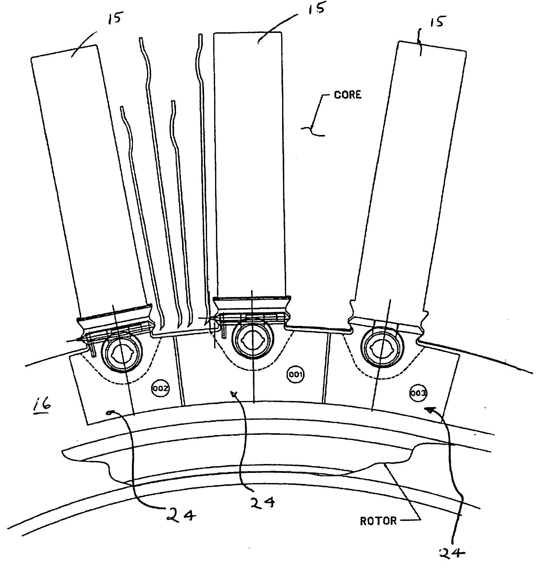
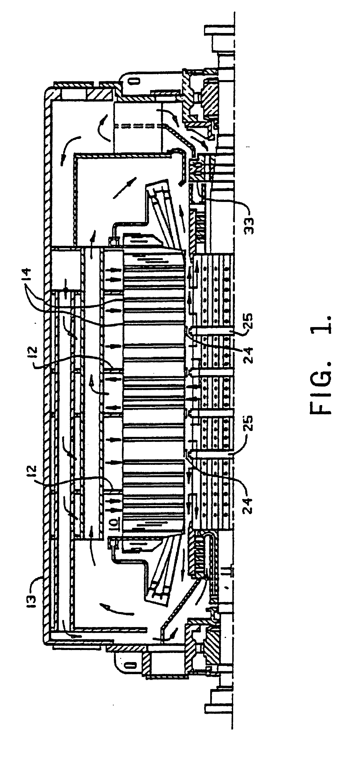
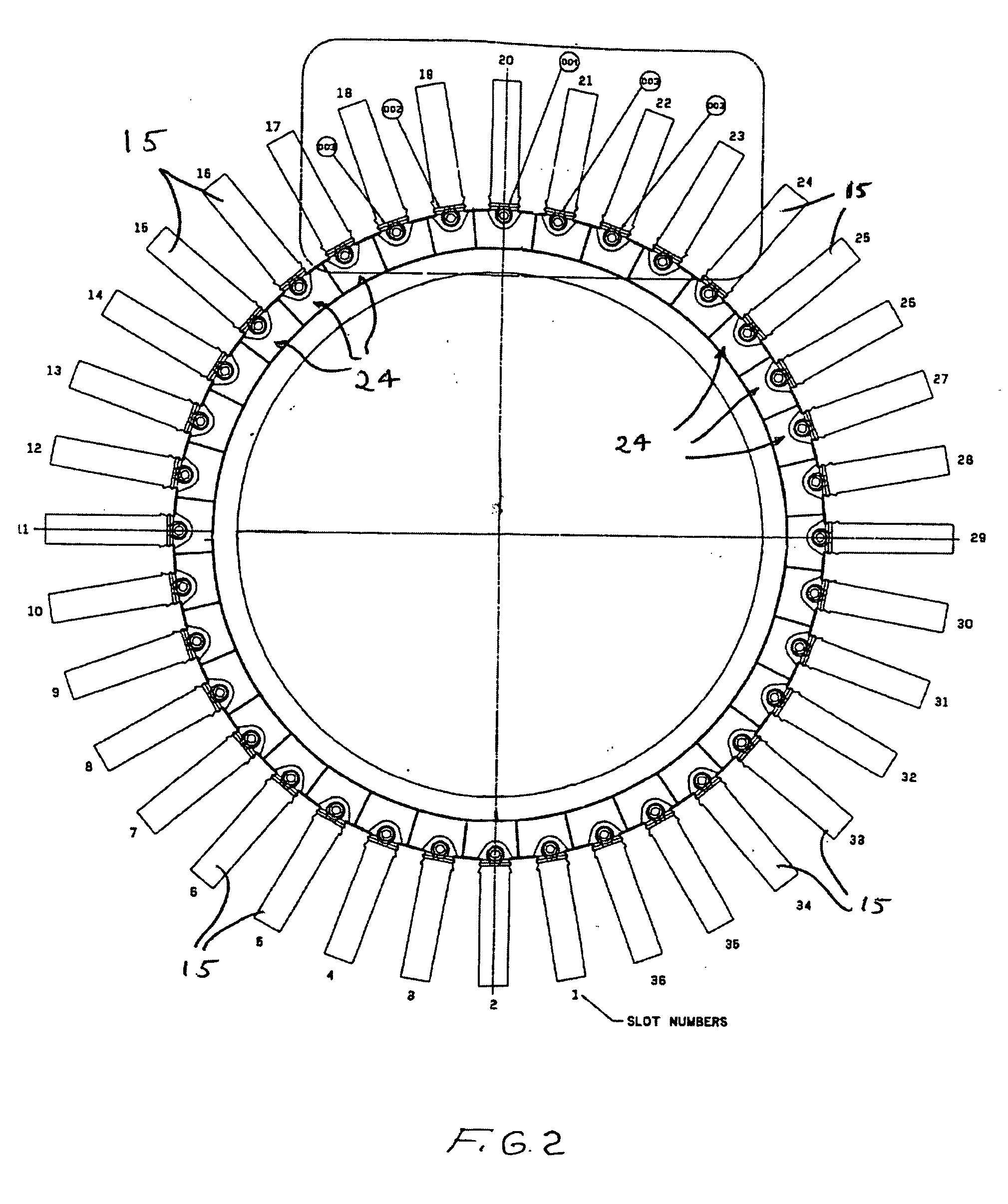
A gas-cooled turbine generator includes a rotor having baffles arranged in rings and defining a plurality of gas cooling zones. A stator core has stator slots in a bore in which the rotor is received. A plurality of air gap baffle assemblies are arranged in segmented baffle rings in the stator slots and cooperate with the zone rings on the rotor. Each of the air gap baffle assemblies includes at least one baffle segment and an individual locking cam cooperating with a respective wedge of the baffle segment to lock the baffle segment relative to a stator slot at which the baffle segment is positioned such that prior baffle “trains” are no longer required.

Description

FIELD OF THE INVENTION [0001] This invention relates generally to the ventilation of gas-cooled turbine generators, and more particularly, this invention relates to an improved method for installing segmented rings of air gap baffles on a stator core and forming cooling zones in a large turbine generator. BACKGROUND OF THE INVENTION [0002] Large turbine generators are constructed in which a coolant gas, usually hydrogen, is circulated through ducts in the stator and rotor slots in direct thermal relation with the current-carrying conductors inside ground insulation. These type of systems are disclosed in commonly assigned U.S. Pat. Nos. 3,110,827; 3,265,912; and 4,751,412. Cooling is accomplished by dividing the air gap formed between the rotor and stator core transversely into a plurality of annular zones by positioning baffles in annular rings in the air gap. These baffles are mounted on the stator core, which oppose rings on the rotor. Typically, there are about five to about eig...

Claims


Application Information

Patent Timeline
IPC IPC(8): H02K9/00H02K9/06H02K9/12H02K15/02
CPCH02K9/005H02K15/02H02K9/12H02K9/00
Inventor ROWE, CHARLES M.LOWTHER, GARY R.
Owner SIEMENS ENERGY INC
Why Eureka
Try Eureka