Eureka AIR delivers breakthrough ideas for toughest innovation challenges, trusted by R&D personnel around the world.

Display controller with display memory circuit

Inactive Publication Date: 2005-06-02
RENESAS ELECTRONICS CORP
View PDF2 Cites 38 Cited by
  • Summary
  • Abstract
  • Description
  • Claims
  • Application Information

AI Technical Summary

Benefits of technology

[0023] Therefore, an object of the present invention is to provide a display controller with a display memory circuit in which the increase of a circuit scale and the increase of consumption power are suppressed regardless of the high precision display and the multi-function achievement.

Problems solved by technology

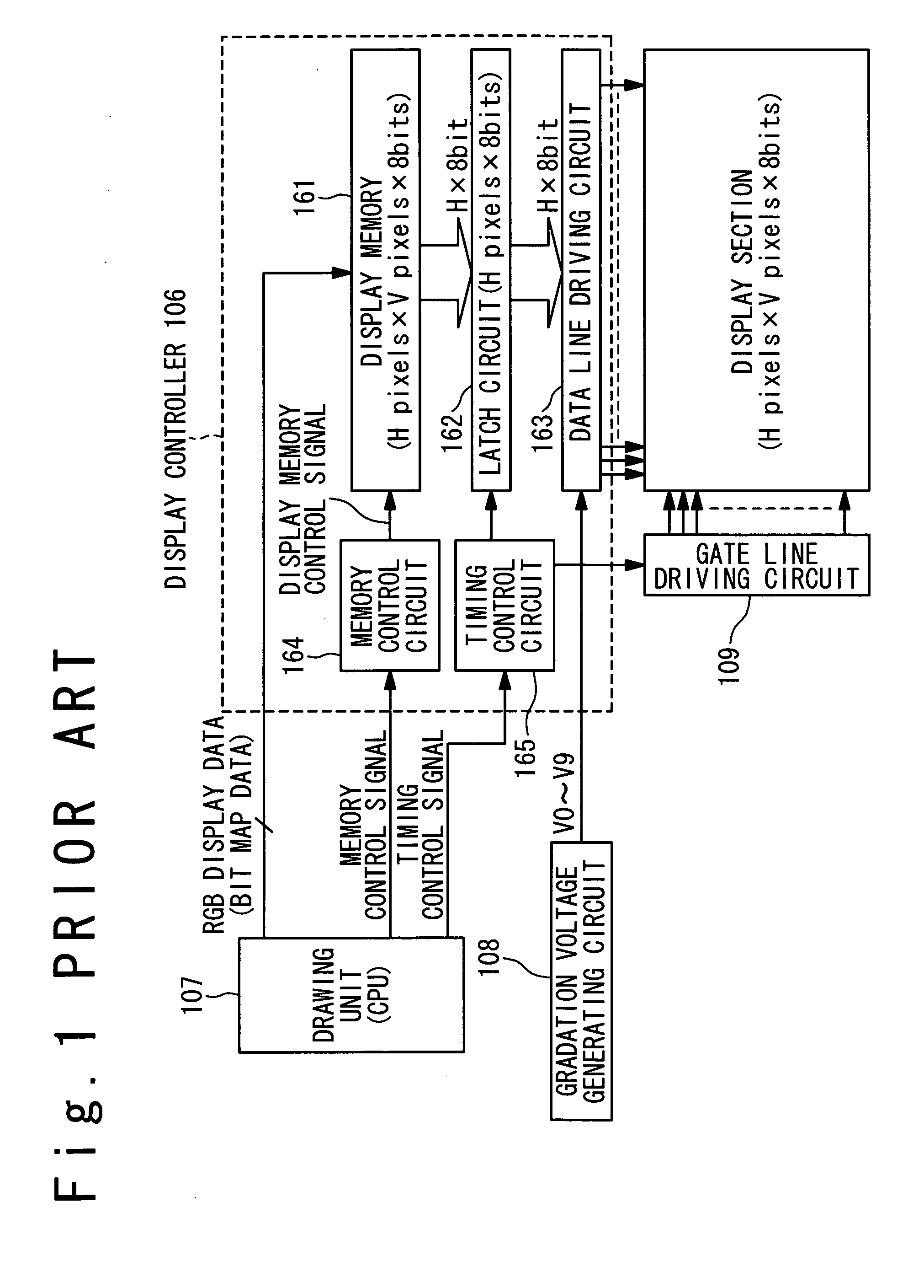
Therefore, the memory capacity of the display memory circuit becomes large, resulting in increase of the circuit scale of the display controller.
Also, a data transfer quantity from the drawing memory to the display memory increases and the consumption power increases.
Especially, since the data are transferred in units of frames between the display controller and the drawing apparatus, the data transfer quantity increases, resulting in increase of the consumption power.
As a result, the battery duration of the portable equipment becomes short.
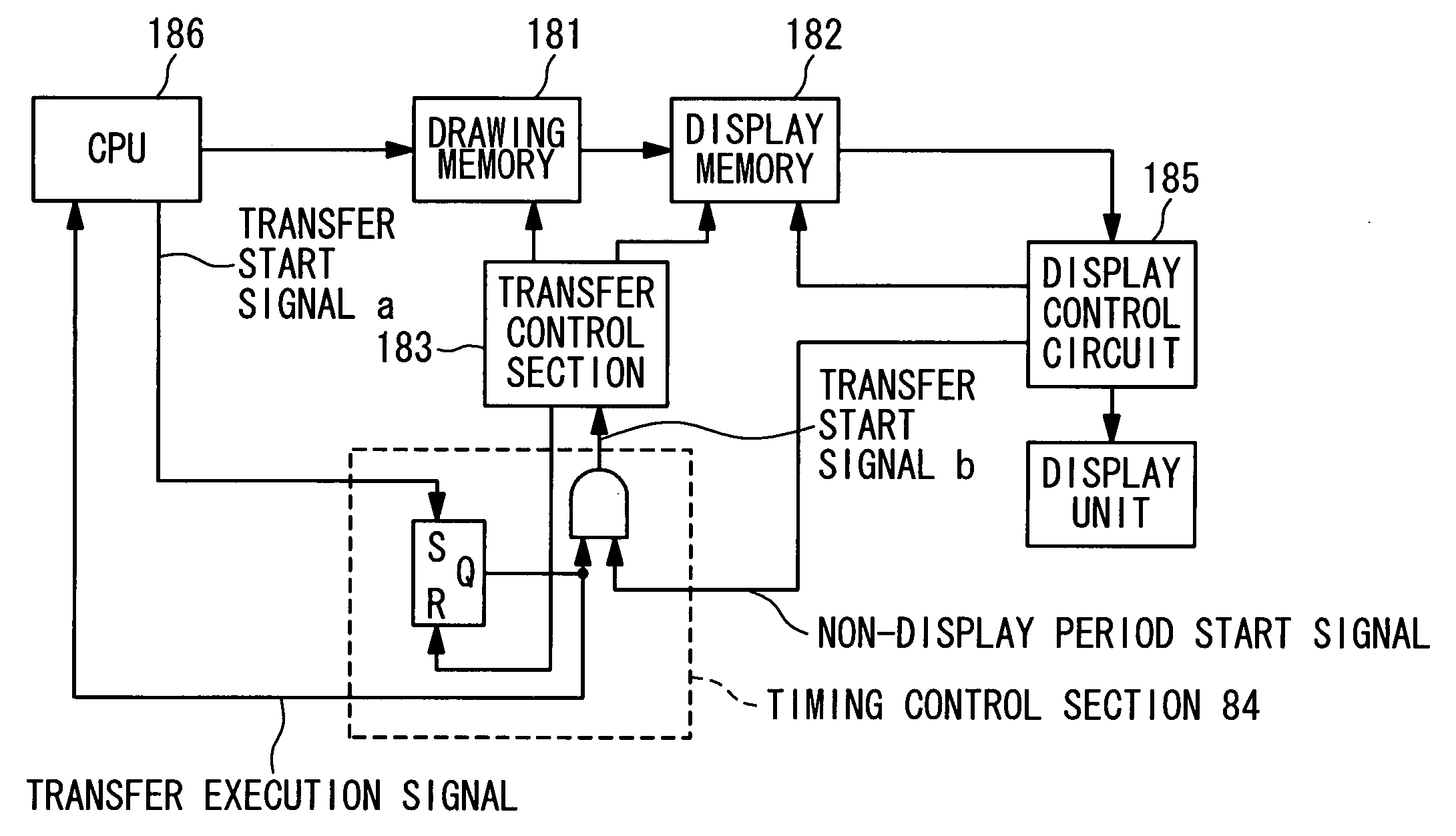
Also, in the display system shown in FIG. 3 and containing the drawing memory and the display memory, the similar problems such as the increase of the circuit scale and the increase of consumption power are caused.

Method used


Image

  • Display controller with display memory circuit
  • Display controller with display memory circuit
  • Display controller with display memory circuit

Examples


Embodiment Construction

[0041] Hereinafter, a display controller with a display memory circuit of the present invention will be described below with reference to the attached drawings.

[0042]FIG. 4 is a block diagram showing a configuration of a display memory circuit according to an embodiment of the present invention. The display memory circuit 1 in the embodiment includes a memory cell array 10, a drawing memory read / write circuit 11, a display memory read circuit 12 and a word control circuit 13.

[0043] In the cell array 10, a plurality of memory cell units are arranged in a matrix. Each of the memory cell units includes a memory cell 101 for the drawing memory, a memory cell 102 for a dynamic display memory, and a buffer 103 (inverter) for buffering data from the memory cell 101 and outputting it to the memory cell 102. The memory cell 101, the memory cell 102 and the buffer 103 are arranged adjacent to each other. It should be noted that only one memory cell unit is shown in FIG. 4. The memory cell 1...


PUM


Abstract

A display memory circuit includes a drawing memory and a dynamic display memory. The drawing memory stores data and at least a portion of the data are possibly rewritten into a new data at a third timing, the third timing being optional between a first timing and a second timing. The dynamic display memory is connected with the drawing memory, which latches the data in response to the first timing and continues to hold the data between the first timing and the second timing. The drawing memory is partially disconnected from the dynamic display memory in the rewritten portion when the portion is rewritten in the drawing memory.

Description

BACKGROUND OF THE INVENTION [0001] 1. Field of the Invention [0002] The present invention relates to a display controller with a display memory circuit, and more particularly to a display controller with a display memory circuit in which a multi-port memory is used. [0003] 2. Description of the Related Art [0004] A conventional display memory circuit is widely used for a display controller or a display system to control a display apparatus to display an image. For instance, in case of a matrix type display apparatus such as a liquid crystal display apparatus, the circuit of a display controller is integrated and installed adjacent to a display panel of the display apparatus. The display controller drives H data lines arranged in parallel to a vertical direction of the display panel directly. [0005]FIG. 1 is a block diagram showing a conventional display controller and a peripheral circuit of the display controller. The display controller 106 includes a display memory 161, a latch ci...

Claims


Application Information

Patent Timeline
IPC IPC(8): G09G3/20G09G3/36G11C11/401G09G5/36G09G5/39G09G5/393G09G5/395G11C7/00G11C7/10G11C11/40G11C11/405
CPCG09G5/393G09G5/395G09G2360/126G11C11/405G11C7/1075G11C8/16G09G2360/18G09G3/20G11C7/10G11C11/40
Inventor SHIODA, JUNYOUNOSE, TAKASHI
Owner RENESAS ELECTRONICS CORP
Why Eureka
Eureka Blog
Learn More