

Image pickup lens system
a technology of image pickup and lens, which is applied in the field of can solve the problems of increased performance required for the image pickup lens system, affecting the brightness of the image, and the lens provided in front of the solid-state image pickup device not exerting enough focusing performance, etc., and achieves compact size and good optical performance.
- Summary
- Abstract
- Description
- Claims
- Application Information
AI Technical Summary
Benefits of technology
Problems solved by technology
Method used
Image

Examples
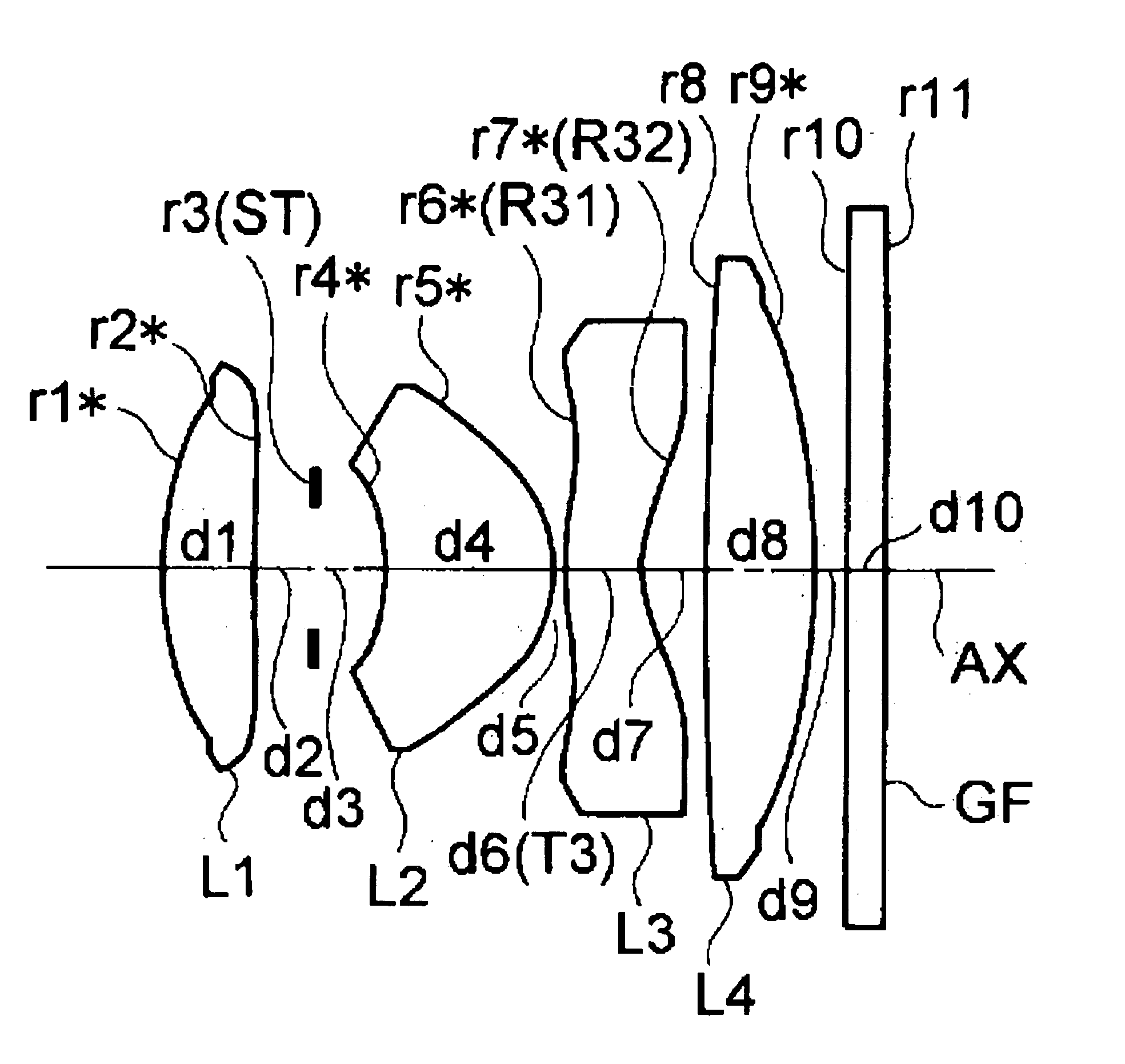
example 1
f=5.795, FNO=3.0
[0071]
radius ofaxialrefractiveAbbecurvaturedistanceindexnumberr1* = 4.228d1 = 1.085N1 = 1.53048ν1 = 55.72(L1)r2* = 47.641d2 = 0.750r3 = ∞(ST)d3 = 0.864r4* = −2.537d4 = 2.024N2 = 1.53048ν2 = 55.72(L2)r5* = −1.495d5 = 0.100r6* = 3.587(=R31)d6 =N3 = 1.58340ν3 = 30.23(L3)0.957(=T3)r7* = 1.531(=R32)d7 = 0.737r8 = 38.075d8 = 1.393N4 = 1.53048ν4 = 55.72(L4)r9* = −15.079d9 = 0.400r10 = ∞d10 = 0.500N5 = 1.51680ν5 = 64.20(GF)r11 = ∞
[aspheric surface data of 1st surface (r1)]
ε = 0.94665, A4 = 0.31003 × 10⁻², A6 = −0.15830 × 10⁻³,
A8 = 0.36453 × 10⁻⁴, A10 = −0.20033 × 10⁻⁴
[aspheric surface data of 2nd surface (r2)]
ε = 0.16000 × 10², A4 = 0.72239 × 10⁻², A6 = −0.41496 × 10⁻²,
A8 = 0.10963 × 10⁻², A10 = −0.15453 × 10⁻³
[aspheric surface data of 4th surface (r4)]
ε = 0.68121, A4 = −0.67380 × 10⁻², A6 = −0.45004 × 10⁻¹,
A8 = 0.29782 × 10⁻¹, A10 = −0.57264 × 10⁻²
[aspheric surface data of 5th surface (r5)]
ε = 0.30436, A4 = 0.11711 × 10⁻¹, A6 = −0.16024 × 10⁻²,
A8 = −0.71809 × 10⁻³, A...
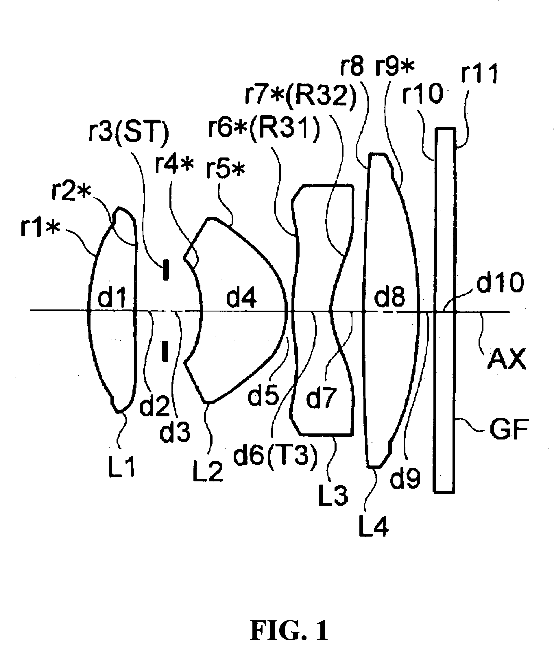
example 2
f=5.667, FNO=3.6
[0072]
radius ofaxialrefractiveAbbecurvaturedistanceindexnumberr1* = 3.863d1 = 0.941N1 = 1.53048ν1 = 55.72(L1)r2* = 29.355d2 = 0.535r3 = ∞(ST)d3 = 1.011r4* = −1.939d4 = 1.381N2 = 1.53048ν2 = 55.72(L2)r5* = −1.381d5 = 0.100r6* = 3.199(=R31)d6 =N3 = 1.58340ν3 = 30.23(L3)0.859(=T3)r7* = 1.562(=R32)d7 = 0.905r8 = 13.704d8 = 1.449N4 = 1.53048ν4 = 55.72(L4)r9* = −31.652d9 = 0.400r10 = ∞d10 = 0.500N5 = 1.51680ν5 = 64.20(GF)r11 = ∞
[aspheric surface data of 1st surface (r1)]
ε = 0.94062, A4 = 0.32704 × 10⁻², A6 = −0.94100 × 10⁻⁴,
A8 = 0.97547 × 10⁻⁴, A10 = −0.81541 × 10⁻⁴
[aspheric surface data of 2nd surface (r2)]
ε = 0.15824 × 10², A4 = 0.77595 × 10⁻², A6 = −0.46503 × 10⁻²,
A8 = 0.97366 × 10⁻³, A10 = −0.18223 × 10⁻³
[aspheric surface data of 4th surface (r4)]
ε = 0.10419 × 10, A4 = −0.70554 × 10⁻², A6 = −0.38890 × 10⁻¹,
A8 = 0.27836 × 10⁻¹, A10 = −0.37367 × 10⁻²
[aspheric surface data of 5th surface (r5)]
ε = 0.32762, A4 = 0.99396 × 10⁻², A6 = −0.48551 × 10⁻²,
A8 = −0.50507 × 10...
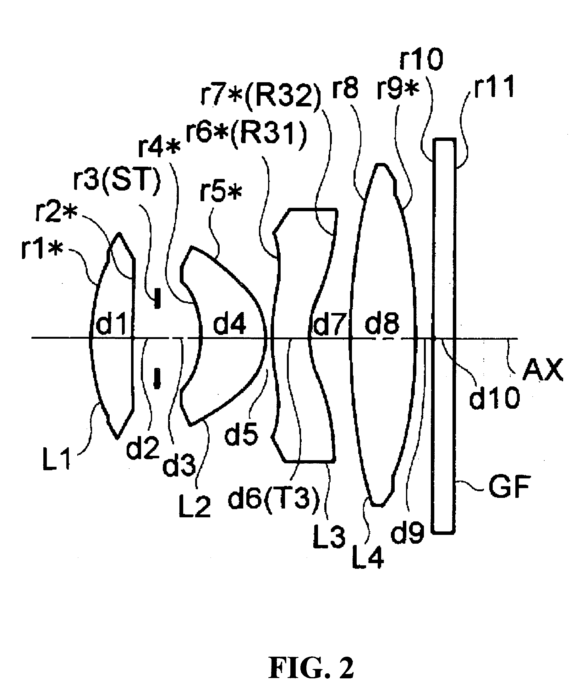
example 3
f=5.761, FNO=3.6
[0073]
radius ofaxialrefractiveAbbecurvaturedistanceindexnumberr1* = 4.495d1 = 0.859N1 = 1.53048ν1 = 55.72(L1)r2* = −129.619d2 = 0.350r3 = ∞(ST)d3 = 1.387r4* = −1.833d4 = 1.179N2 = 1.53048ν2 = 55.72(L2)r5* = −1.286d5 = 0.100r6* = 3.814(=R31)d6 =N3 = 1.58340ν3 = 30.23(L3)1.065(=T3)r7* = 1.536(=R32)d7 = 0.638r8* = −54.069d8 = 1.602N4 = 1.53048ν4 = 55.72(L4)r9 = −6.406d9 = 0.400r10 = ∞d10 = 0.500N5 = 1.51680ν5 = 64.20(GF)r11 = ∞
[aspheric surface data of 1st surface (r1)]
ε = 0.19577, A4 = 0.89873 × 10⁻³, A6 = 0.47746 × 10⁻³,
A8 = −0.29347 × 10⁻⁴, A10 = −0.13868 × 10⁻⁴
[aspheric surface data of 2nd surface (r2)]
ε = −0.14000 × 10², A4 = 0.50318 × 10², A6 = −0.34046 × 10⁻²,
A8 = 0.22696 × 10⁻², A10 = −0.62563 × 10⁻³
[aspheric surface data of 4th surface (r4)]
ε = 0.86631, A4 = 0.86947 × 10⁻², A6 = −0.37774 × 10⁻¹,
A8 = 0.22545 × 10⁻¹, A10 = −0.24441 × 10⁻²
[aspheric surface data of 5th surface (r5)]
ε = 0.28368, A4 = 0.17020 × 10⁻¹, A6 = −0.71164 × 10⁻²,
A8 = −0.24640 × 10⁻³, ...
PUM
 Abstract
Description
Claims
Application Information