
Transmitter identification system

Active Publication Date: 2005-06-02
GULA CONSULTING LLC
View PDF33 Cites 76 Cited by
  • Summary
  • Abstract
  • Description
  • Claims
  • Application Information

AI Technical Summary

Problems solved by technology

Unfortunately, the various components of the transmitted signal may not all be in phase, resulting in undesired effects.
The effects of multi-path interference to DTV signals include a degradation in the television picture and sound.
In analog television, multi-path interference causes “ghost” images.
Unfortunately, none of the prior art references provide an identification signal for each transmitter, nor do they provide a system for tuning the entire network.
Each of the aforementioned systems requires a complicated filtering circuit to be installed in every receiver in the system, which greatly increase the cost to the operator, and therefore the consumer.
Conventional Global Positioning Systems (GPS) do not work well inside buildings, due to the weak field strength and the high frequency of the GPS signal.

Method used


Image

  • Transmitter identification system
  • Transmitter identification system
  • Transmitter identification system

Examples


Embodiment Construction

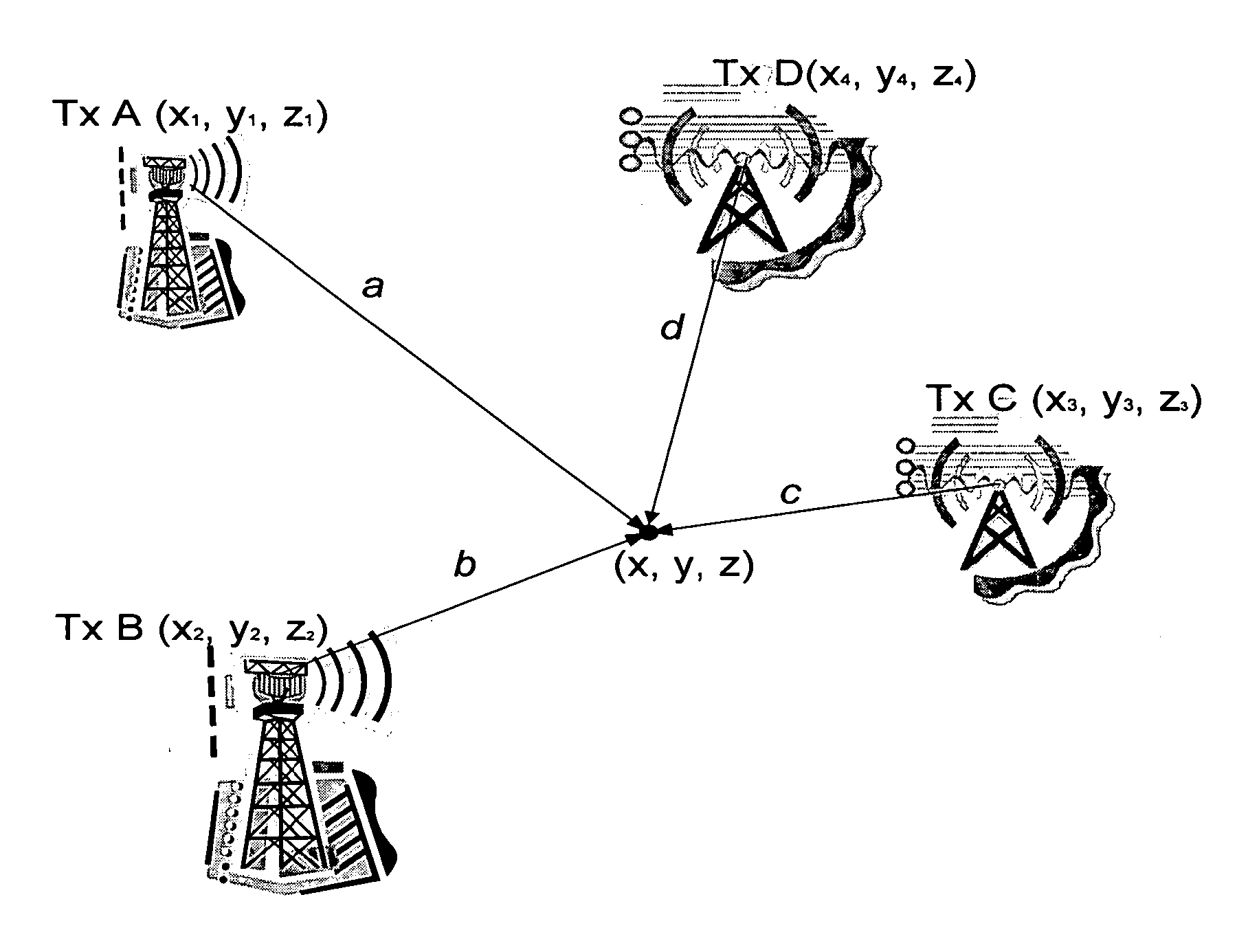
[0025] In accordance with the present invention, the transmitter identification system embeds an identification sequence in the form of a pseudo-random sequence xi(n), selected from a set of orthogonal sequences, in band into each DTV signal di(n) creating a combined transmission di′(n). In practice, the sequences will be truncated and, therefore, not be perfectly orthogonal; however, for the purposes of the invention they will only need to have negligible cross correlation. Accordingly, orthogonal, substantially-orthogonal and having negligible cross correlation will be used interchangeably so as not to limit the scope of protection to perfectly orthogonal.

[0026] The process is represented by the equation:

di′(n)=di(n)+μxi(n)  (1)

[0027] wherein ρ represents a gain coefficient controlling the embedding level of the identification sequence, which varies from transmitter to transmitter depending on the modulation and channel coding schemes of the individual transmitters. After passi...


PUM


Abstract

The invention relates to a transmitter identification system, which utilizes an identification signal embedded into a digital television signal, enabling the transmitter of origin to be identified at a receiving station. Ideally the identification signal is an orthogonal pseudo-random sequence time synchronized to the signal frame structure of the digital television signal. Particularly designed for single frequency networks, identification of the various transmitted signals enables the network to be tuned to eliminate or minimize multi-path effects at certain locations, which receive transmissions from various transmitters.

Description

CROSS-REFERENCE TO RELATED APPLICATIONS [0001] The present application is a continuation-in-part of U.S. patent application Ser. No. 10 / 765,138 filed Jan. 28, 2004, which claims priority from U.S. patent application Ser. No., 60 / 443,550 filed Jan. 30, 2003, which are all incorporated herein by reference.TECHNICAL FIELD [0002] The present invention relates to a transmitter identification system, and in particular to a digital television (DTV) transmitter identification system for identifying the origin of a received DTV signal, which can be used for tuning a distributed-transmission (single-frequency) DTV network, geographic locating, estimating the channel impulse response for a particular transmitter with a very long delay spread capacity, and transmitting robust low bit rate control information to mobile and stationary terminals. BACKGROUND OF THE INVENTION [0003] Digital television (DTV) networks are comprised of a plurality of transmitters, each broadcasting the same signal usin...

Claims


Application Information

Patent Timeline
IPC IPC(8): G01S19/46G01S19/24G01S19/36H04N5/44H04N7/087H04N7/16H04N7/173
CPCH04H20/30H04H20/67H04H20/72H04H60/74H04N21/6112H04N21/23614H04N21/26241H04N21/4348H04N21/438H04N21/235
Inventor WU, YIYANWANG, XIANBINLAFLECHE, SEBASTIENLEDOUX, BENOITCARON, BERNARD
Owner GULA CONSULTING LLC
Learn More