Wireless transmission using an adaptive transmit antenna array

a technology of transmit antenna array and wireless transmission, applied in the field of closed loop wireless transmission of signals using an adaptive transmit antenna array, can solve the problems of delay and attenuation factor change as well

Active Publication Date: 2005-06-02
GOOGLE TECH HLDG LLC
View PDF30 Cites 322 Cited by
  • Summary
  • Abstract
  • Description
  • Claims
  • Application Information

AI Technical Summary

Problems solved by technology

In practice, movement of a mobile receiver will change the scattering environment and thus the delays and attenuation factors will change as well.

Method used


Image

  • Wireless transmission using an adaptive transmit antenna array
  • Wireless transmission using an adaptive transmit antenna array
  • Wireless transmission using an adaptive transmit antenna array

Examples


Embodiment Construction

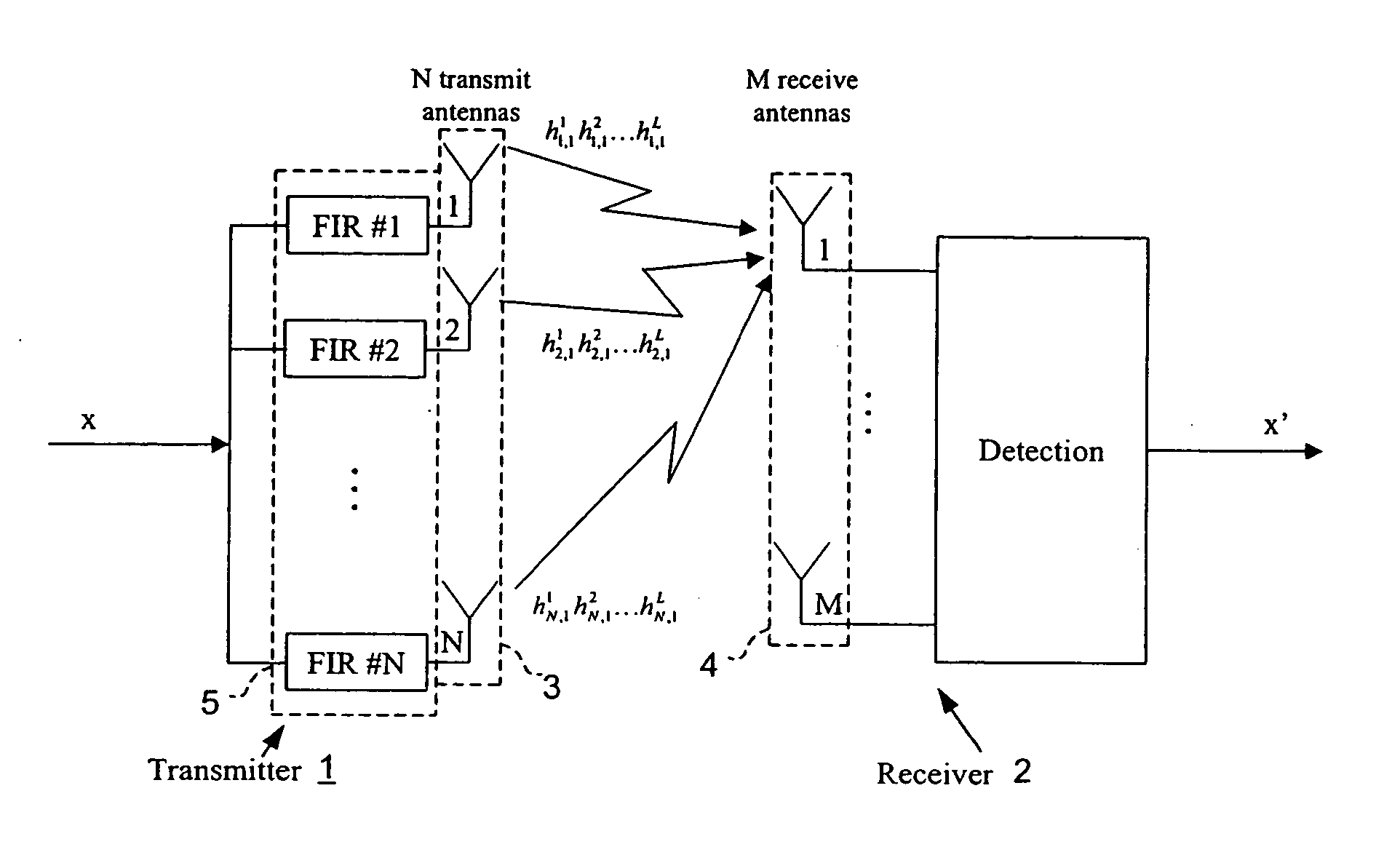
[0021]FIG. 1 shows a first embodiment of a system for transmitting data by a transmit diversity wireless communication network, the system comprising a first station 1 that will be described as the transmitter side (with primary reference to its transmission function) and a second station 2 that will be described as the receiver side (with primary reference to its reception function). In the present case, the first station 1 and the second station 2 are both capable of both transmission and reception and, moreover, the same antenna elements are used both for transmission and reception in the preferred embodiment of the invention.

[0022] The transmitter side 1 comprises an array 3 of N transmit antenna elements. The receiver side 2 of the system comprises an array 4 of M receive antenna elements. The number of antenna elements on each side is chosen as a compromise between economical considerations and the technical desirability to provide increased channel diversity. In the case of ...


PUM


Abstract

Closed loop wireless communication of signals using an adaptive transmit antenna array (3), in which a plurality of copies of signals to be transmitted by the transmit antenna array (3) are produced with delays and weights (wnj) that are functions of the multi-path transmission channel characteristics (H) from the transmit antenna array (3) to a receive antenna array (4) of a receiver (2) and are combined before transmission by the transmit antenna array. The delays and weights (wnj) of the transmit copies for each transmit antenna element are functions of the respective multi-path transmission channel characteristics (hn,m=1l=1,,hn,m=Ml=L)
from that transmit antenna element to the receive antenna array (4) ssuch that the multi-path signal components propagated to each receiver element are received with distinguishable delays according to the propagation path. The receiver (2) combines the received signal components from each receive antenna element with delays and weights (u) that are respective functions of the multi-path transmission channels.
Preferably, the receiver comprises a multi-finger RAKE receiver (6) that copies the received signals from the receive antenna array with delays and weights (u) that are respective functions of the multi-path transmission channels and combines the copied received signals.

Description

FIELD OF THE INVENTION [0001] This invention relates to closed loop wireless transmission of signals using an adaptive transmit antenna array and is particularly suitable for transmission in a delay-spread environment. BACKGROUND OF THE INVENTION [0002] Wireless communication systems are assuming ever-increasing importance for the transmission of data, which is to be understood in its largest sense as covering speech or other sounds and images, for example, as well as abstract digital signals. [0003] Currently proposed standards for wireless communication systems include the 3GPP (3rd generation Partnership Project) and 3GPP2 standards, which use Code Division Multiple Access (‘CDMA’) and Frequency Division Duplex (‘FDD’) or Time Division Duplex (‘TDD’), the HIPERLAN and HIPERLAN2 local area network standards of the European Telecommunications Standards Institute (‘ETSI’), which use Time Division Duplex (‘TDD’) and the International Telecommunications Union (‘ITU’) IMT-2000 standard...

Claims


Application Information

Patent Timeline
Patent Type & Authority Applications(United States)
IPC IPC(8): H04B1/707H04B7/04H04B7/06H04B7/08
CPCH04B1/7115H04B7/0634H04B7/0639H04B7/0654H04L25/0204H04B7/0673H04B7/0845H04B7/0854H04B7/0891H04B7/0671
Inventor VIALLE, SANDRINEWHINNETT, NICHOLASBULJORE, SOODESH
Owner GOOGLE TECH HLDG LLC
Why Eureka
Try Eureka