
Method and apparatus for transforming a high dynamic range image into a low dynamic range image

a high dynamic range image and low dynamic range technology, applied in the field of image processing methods, can solve the problems of insufficient hdr image data corresponding dynamic range of prior art format, inability to capture and render high dynamic range images, and full visual artifacts in human vision, so as to improve image processing performance, improve the contrast of pixels originally with luminance value in the middle luminance range, and improve the effect of the claimed method

Inactive Publication Date: 2005-06-02
INVENTEC APPLIANCES CORP
View PDF3 Cites 122 Cited by
  • Summary
  • Abstract
  • Description
  • Claims
  • Application Information

AI Technical Summary

Benefits of technology

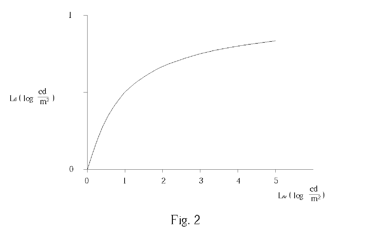
[0013] It is an advantage of the present invention that a film transfer S-curve is utilized. The resulting LDR image is a realistic-looking photograph without the visual artifacts, and the final LDR image shown on the standard display device is clear. With the help of the film transfer S-curve, contrast for pixels originally with luminance value in the middle luminance range is improved, and corresponding details are clearly shown. In addition, the film transfer S-curve is pre-defined, and is not calculated during the tone mapping process. Therefore, it is easier to implement the claimed method, and the image processing performance is better than before.
[0014] These and other objectives of the present invention will no doubt become obvious to those of ordinary skill in the art after reading the following detailed description of the preferred embodiment, which is illustrated in the various figures and drawings.

Problems solved by technology

Currently, there is no simple and direct method to capture and render the high dynamic range images.
It is obvious that the corresponding dynamic range of the prior art format is insufficient for the HDR image data.
However, the human vision is full of visual artifacts such as glares at higher luminance and blurs at lower luminance.
Therefore, the prior art tone mapping process will introduce the visual artifacts inherent in human vision into the LDR image rendered from the HDR image.
Though the final LDR image shown on the standard display device corresponds to what an observer sees the captured scene, the image quality is degraded owing to the introduced visual artifacts.
In addition, it requires complicated real-time calculation to add the wanted visual artifacts into the LDR image, and the time-consuming computation certainly leads to poor image processing efficiency.

Method used


Image

  • Method and apparatus for transforming a high dynamic range image into a low dynamic range image
  • Method and apparatus for transforming a high dynamic range image into a low dynamic range image
  • Method and apparatus for transforming a high dynamic range image into a low dynamic range image

Examples


Embodiment Construction

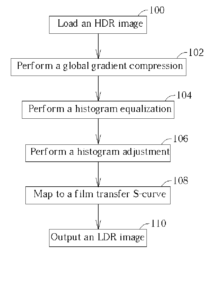
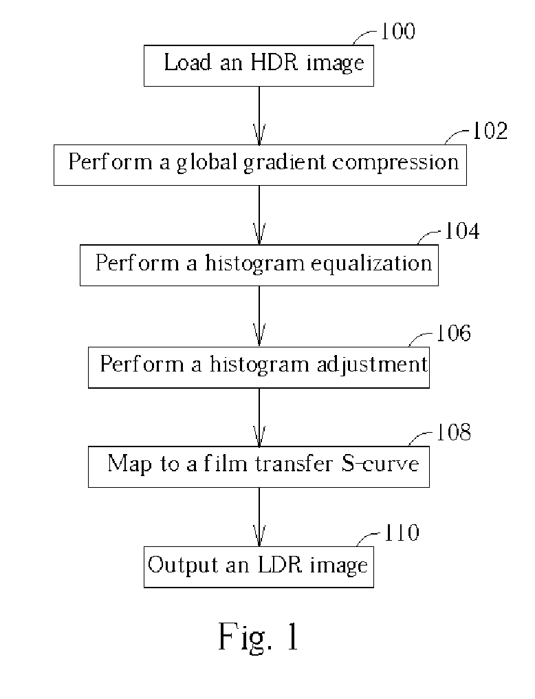
[0019] Please refer to FIG. 1, which is a flow chart of the tone mapping process according to the present invention. The tone mapping process according to the present invention is described as follows. First, an HDR image is loaded (step 100). The HDR image, as mentioned above, is generated from a plurality of images captured at different exposures, and the HDR image corresponds to a wide dynamic range greater than that of a standard display device. Therefore, the original dynamic range of the inputted HDR image needs to be compressed into a new low dynamic range available to the standard display device. In addition, the human visual system is not very sensitive to absolute luminance, but rather responds to local luminance changes and reduces the effect of large global illumination differences. Therefore, a global gradient compression is performed to compress the original dynamic range and reduce the global illumination differences. In order to simplify computation complexity and im...


PUM


Abstract

A method and an apparatus for transforming a high dynamic range image into a low dynamic range image. The method includes converting first luminance values associated with pixels into a plurality of second luminance values, and utilizing a film transfer function for mapping the second luminance values associated with the pixels into a plurality of third luminance values to generate the low dynamic range image. A second luminance range of the second luminance values is smaller than a first luminance range of the first luminance values, and the film transfer function adds no visual artifact to the low dynamic range image.

Description

BACKGROUND OF INVENTION [0001] 1. Field of the Invention [0002] The present invention relates to an image processing method. In particular, the present invention discloses a method and an apparatus for transforming a high dynamic range image into a low dynamic range image. [0003] 2. Description of the Prior Art [0004] The dynamic range of a scene is defined to be a ratio of the highest scene luminance to the lowest scene luminance. Generally speaking, a standard display device such as a CRT monitor or an LCD monitor has a dynamic range of about 250:1, and covers about half of the visible color gamut. However, the human vision system (HVS) has a dynamic range greater than 10,000:1, and is capable of distinguishing about 10,000 colors at a given brightness. In addition, a computer-generated image (CGI) commonly has a factor of 3000 between the highest and lowest intensity values. [0005] Typically, the image displayed on the standard display device corresponds to intensities spanning 2...

Claims


Application Information

Patent Timeline
IPC IPC(8): G06K9/00G06T5/40
CPCG06T5/009G06T2207/20208G06T5/40G06T5/92
Inventor FUH, CHIOU-SHANNFOO, CHIK-YAUKAO, CHAO-YANG
Owner INVENTEC APPLIANCES CORP
Learn More