Induction heating type of fixing device and image forming apparatus equipped therewith

a fixing device and fixing technology, applied in the direction of electric/magnetic/electromagnetic heating, instruments, electrographic processes, etc., can solve the problems of induction coils generating noise, coils generating small vibrations, unwanted temperature rise, etc., to improve the safety of energization control, easy and fast signal switching, and efficient heating of heating rollers without time loss

Inactive Publication Date: 2005-06-02
KONICA MINOLTA BUSINESS TECH INC
View PDF8 Cites 17 Cited by
  • Summary
  • Abstract
  • Description
  • Claims
  • Application Information

AI Technical Summary

Benefits of technology

[0032] This can stop energization of driving currents to the induction coils when the control means runs away or when a cable is grounded. As the result, this can improve the safety of energization control of the induction heating type of fixing device.
[0033] According to Structures (6) and (12), the switching signal is a PWM signal. This enables easy and fast signal switching and efficient heating of the heating roller without a time loss. This can also enables the use of a switching signal for detection of abnormality.

Problems solved by technology

This configuration has caused various problems such as uneven surface temperature of the heating roller along the roller axis and unwanted temperature rises at roller surfaces where a recording material of a smaller size (than the maximum width of the recording material) does not pass by.
Therefore, if the adjoining induction coils are energized simultaneously, driving currents of different frequencies flow through the induction coils and cause the coils to generate small vibrations.
Further, this vibration resonates the heating roller and as the result, the induction coils generate noises such as resonant noises.
When the induction coils are not energized simultaneously, the temperature of the heating member may drop because of a loss time during which the heating member is not heated by the induction coils.
This temperature drop causes a fixing trouble and a reduction in the heating rate of the heating member.

Method used


Image

  • Induction heating type of fixing device and image forming apparatus equipped therewith
  • Induction heating type of fixing device and image forming apparatus equipped therewith
  • Induction heating type of fixing device and image forming apparatus equipped therewith

Examples


embodiment

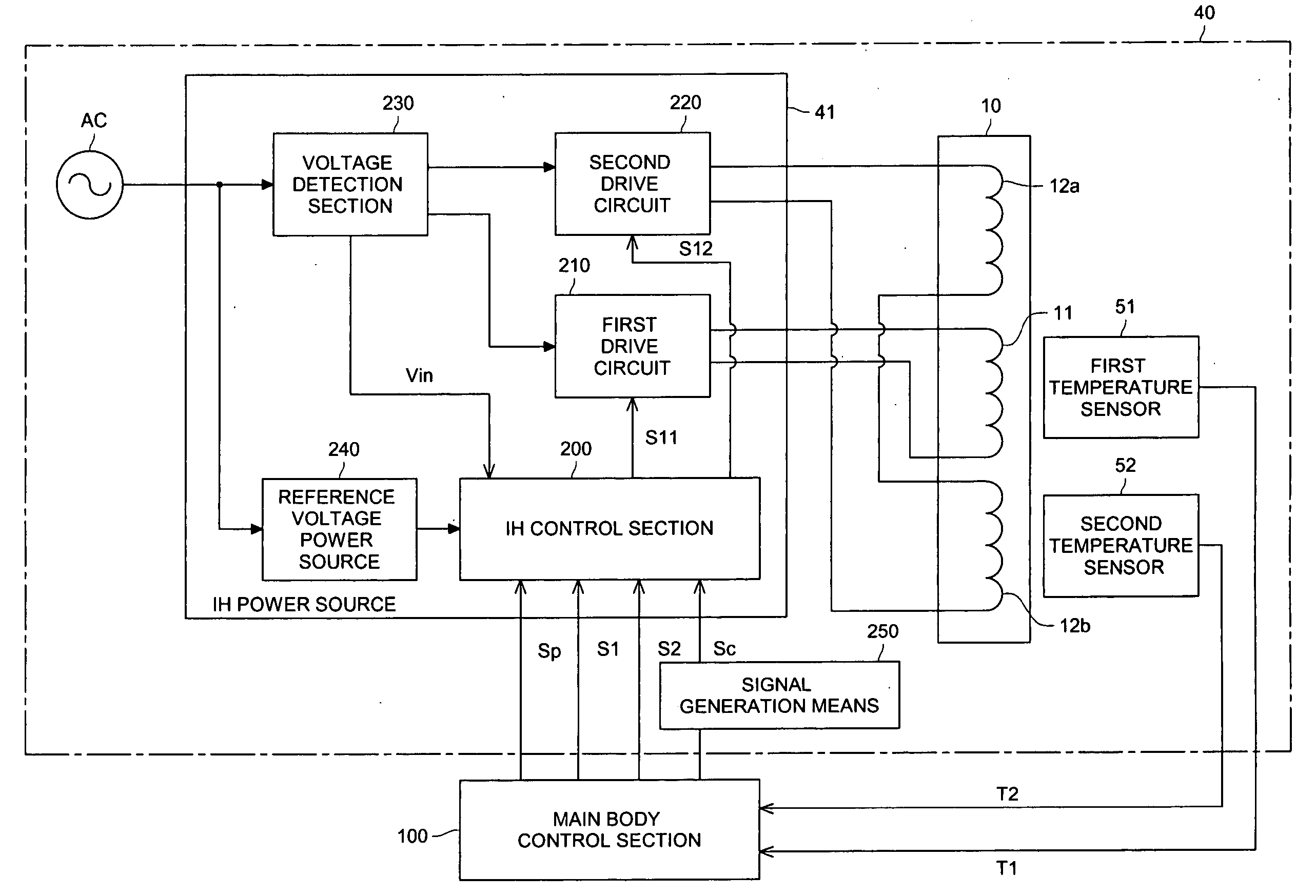
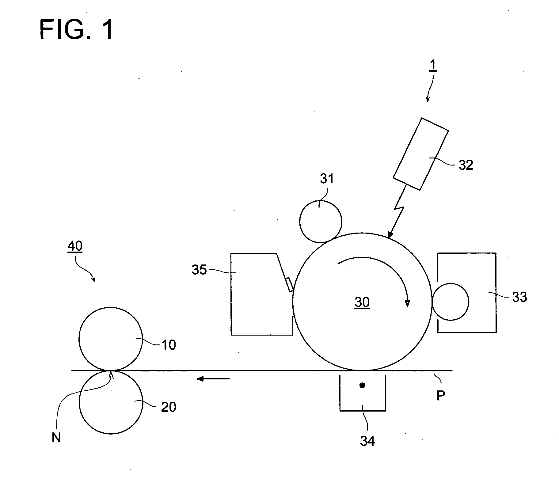
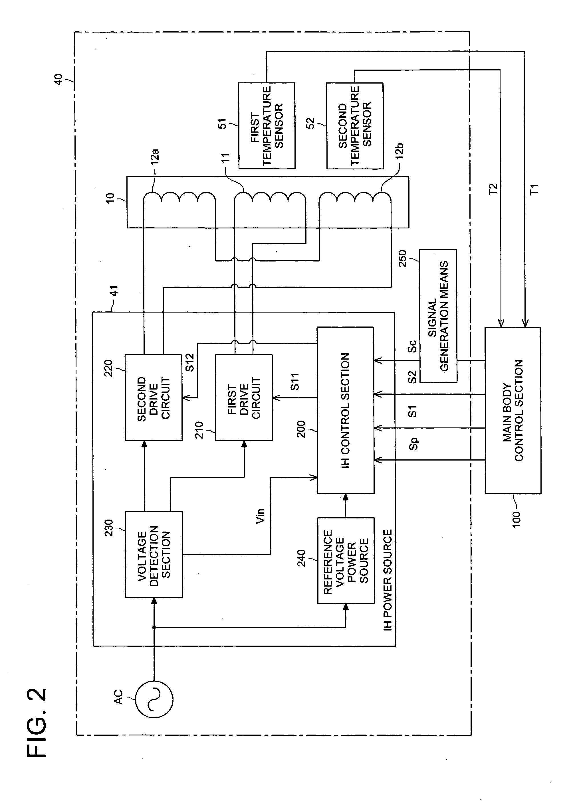
Configuration of the Image Forming Apparatus

[0045] The image forming apparatus of this invention has an image carrier for carrying a toner image, a transfer means for transferring a toner image from the image carrier to a recording material, and an induction heating type of fixing device for thermally fixing the recording material having a toner image on it. The image carrier can be a photosensitive material or intermediate transfer member.

[0046] As shown in FIG. 1, the image forming apparatus is equipped with a photosensitive drum 30 as an image carrier and takes the steps of applying a preset potential to the surface of the photosensitive drum 30 by a charger 31, exposing an image to the surface of the photosensitive drum 30 by the exposing means 32 to form a latent image thereon, developing the latent image with a developing agent containing a toner and a carrier to make it visible, by a developer 33, transferring the visible toner image to a recording material P such as paper...


PUM


Abstract

An induction heating type of fixing device to fix a recording material having a toner image thereon, having a heating member, an induction coil divided into a plurality of parts, a temperature detector for detecting a temperature of the heating member, a signal generator for generating a switching signal that periodically controls permission and prohibition of energization of each of the divided induction coils, and a controller for controlling supply of a driving current to each of the divided induction coils to heat the heating member. The controller controls the energization by periodically switching the driving current to each of the divided induction coils on the basis of an energization signal that determines the permission and the inhibition of the driving currents according to a signal of temperature detected by the temperature detector, and the switching signal.

Description

BACKGROUND OF THE INVENTION [0001] This invention relates to an induction heating type of fixing device and an image forming apparatus equipped therewith such as copy machine, printer and facsimile equipment. More particularly, this invention relates to energization control of an induction heating type of fixing device. [0002] The image forming apparatus is equipped with a fixing device that thermally fixes toner images on a recording material. An induction heating type of fixing device is equipped with an electroconductive heating roller including an induction coil as a heat source and a pressing roller that is pressed against the heating roller and forms a nip section. [0003] The induction coil is as long as the maximum width of the recording material to heat the whole heating roller (maximum width of the recording material). This configuration has caused various problems such as uneven surface temperature of the heating roller along the roller axis and unwanted temperature rises ...

Claims


Application Information

Patent Timeline
Patent Type & Authority Applications(United States)
IPC IPC(8): G03G15/20
CPCG03G15/2039
Inventor SASAMOTO, YOSHIHITOKAWAMOTO, KIYOAKITAKAHASHI, ATSUSHIMATSUMOTO, HIROSHIKUROSU, TETSUKOTANAKA, HIDEAKIHANYU, NAOHIKOISOBE, AKIFUMI
Owner KONICA MINOLTA BUSINESS TECH INC
Why Eureka
Try Eureka