Ultrasound diagnosis apparatus

a technology of ultrasound and diagnostic equipment, applied in the field of ultrasound diagnostic equipment, can solve the problems of not being able to easily find the optimum probe position and the optimum probe orientation, and not being able to disclose a technique, etc., and achieve the effect of reducing the load of the user

Inactive Publication Date: 2005-06-02
HITACHI LTD
View PDF21 Cites 71 Cited by
  • Summary
  • Abstract
  • Description
  • Claims
  • Application Information

AI Technical Summary

Benefits of technology

[0009] The present invention advantageously provides an ultrasound diagnosis

Problems solved by technology

None of the references, however, discloses a technique for supporting a probe operation to match the current diagnosis part to the past diagnosis part.
In addition, even for an expert user, the probe operations are complex.
Further, even for an expert user, the optimum probe position and the optimum probe orientation may not be easily found.
In particular, when the user during the

Method used


Image

  • Ultrasound diagnosis apparatus
  • Ultrasound diagnosis apparatus
  • Ultrasound diagnosis apparatus

Examples


Embodiment Construction

[0028] A preferred embodiment (hereinafter referred to simply as “embodiment”) of the present invention will now be described.

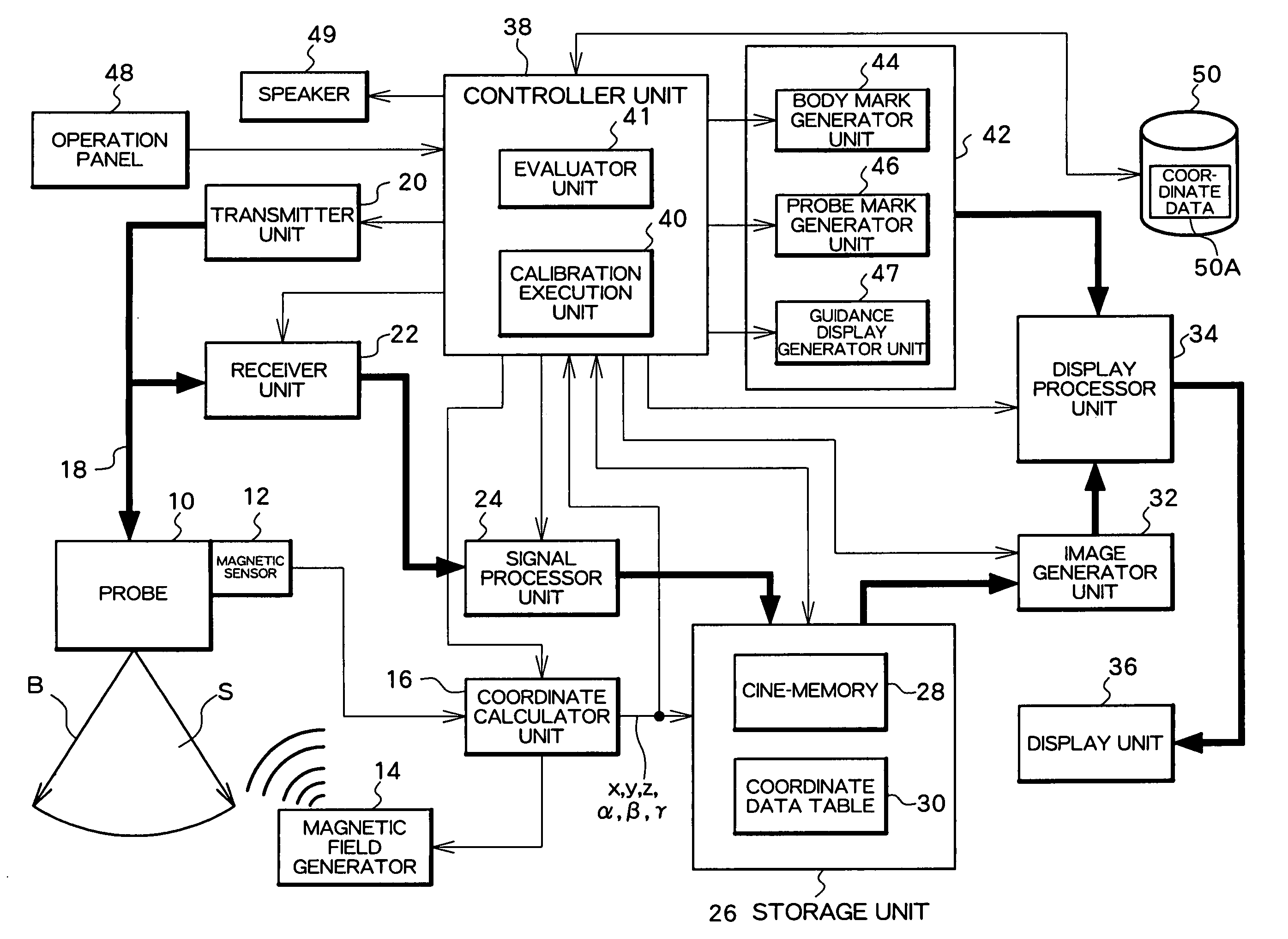
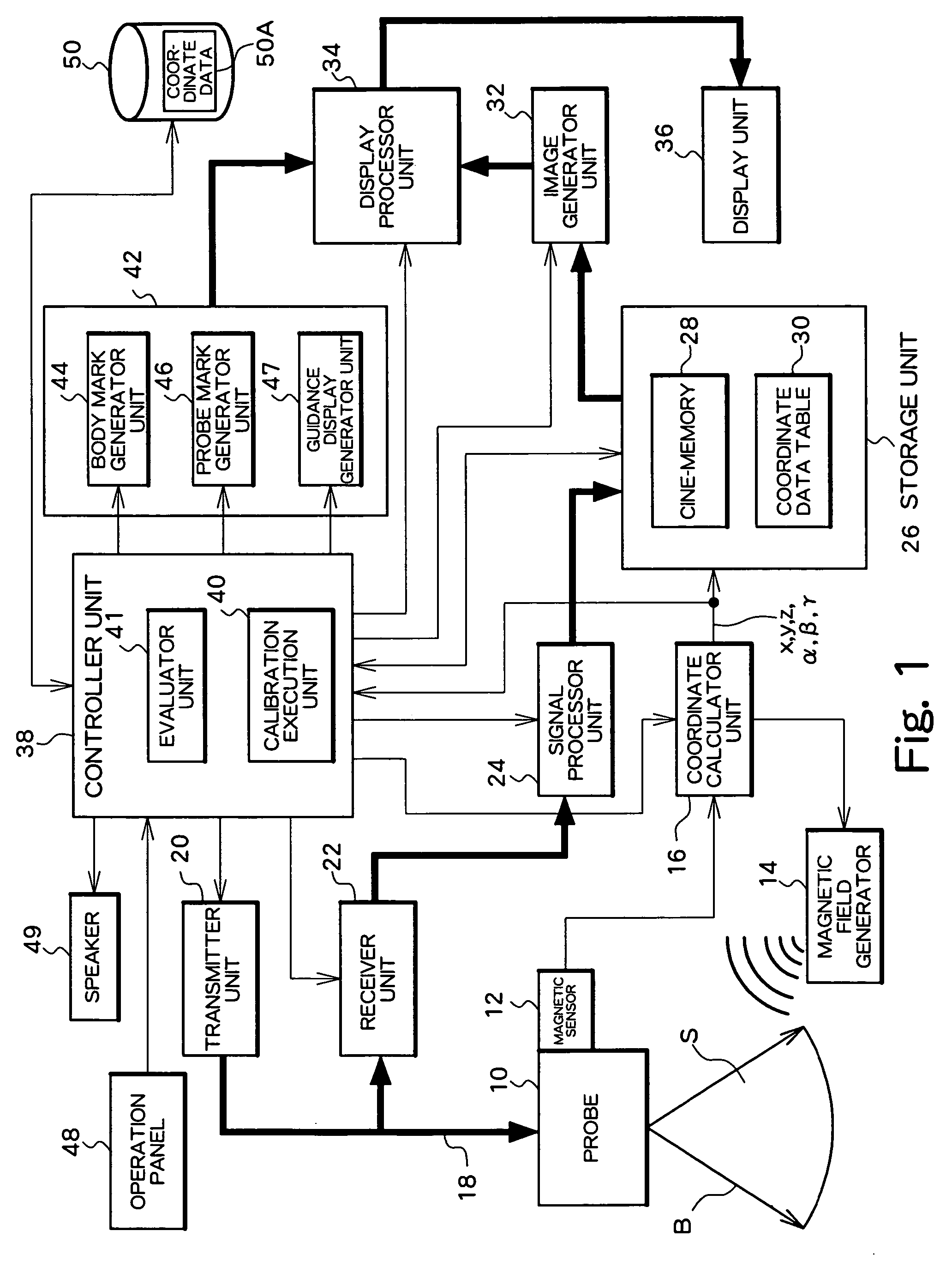
[0029]FIG. 1 is a block diagram showing an overall structure of an ultrasound diagnosis apparatus according to a preferred embodiment of the present invention. As will be described later, the ultrasound diagnosis apparatus has a function to display a reference image, a function to display a guidance display, etc. for supporting operations of the probe by the user.

[0030] A probe 10 is a transportable device for transmitting and receiving ultrasound. The probe 10 has a transducer array including a plurality of transducer elements in the structure exemplified in FIG. 1. The transducer array generates an ultrasound beam B. By electronically scanning with the ultrasound beam B, a two-dimensional scanning plane S is generated. As a method of electronic scanning, it is possible to employ, for example, an electronic sector scanning system or an electronic linear sc...


PUM


Abstract

In a medical ultrasound diagnosis apparatus, a reference image and a guidance display are provided as probe operation support information. The reference image contains a recorded probe mark generated based on coordinate data recorded during a past diagnosis and a current probe mark generated based on current coordinate data. A user adjusts a position and an orientation of a probe so that these marks match. The guidance display has a plurality of indicators provided corresponding to a plurality of coordinate components. Each indicator displays proximity and match for each coordinate component. With the probe operation support information, it is possible to quickly and easily match a current diagnosis part to a past diagnosis part.

Description

BACKGROUND OF THE INVENTION [0001] 1. Field of the Invention [0002] The present invention relates to an ultrasound diagnosis apparatus, and in particular to a technique for supporting a probe operation (position and / or orientation adjustment) by a user. [0003] 2. Description of the Related Art [0004] An ultrasound diagnosis apparatus has a function to display, on a screen of a display device, “a body mark (body symbol)” and a “probe mark (probe symbol)” as reference images along with an ultrasound image (image of living tissue, or living body image). The body mark is typically a simple, two-dimensional figure schematically representing a partial shape within a living body. A user may operate the device to select a specific body mark corresponding to a body part to be diagnosed using ultrasound from among a plurality of body marks which are prepared in advance. The body mark is displayed near the living body image. In order to identify a position and direction of the probe during ult...

Claims


Application Information

Patent Timeline
IPC IPC(8): A61B8/00G01S7/52
CPCA61B8/00A61B8/42A61B8/4254G01S7/52073G01S7/52023G01S7/52068A61B8/463
Inventor OHTAKE, AKIFUMI
Owner HITACHI LTD
Why Eureka
Try Eureka