Prostheses, systems and methods for replacement of natural facet joints with artificial facet joint surfaces

a technology of facet joints and prostheses, applied in the field of prostheses for treating various types of spinal pathologies, can solve the problems of affecting the function of the prosthesis, affecting the quality of life of the patient, etc., to achieve secure and durable attachment to cortical and/or cancellous bone, secure and stabilize the prosthesis, and improve the effect of quality of li

Inactive Publication Date: 2005-06-02
GLOBUS MEDICAL INC
View PDF99 Cites 186 Cited by
  • Summary
  • Abstract
  • Description
  • Claims
  • Application Information

AI Technical Summary

Benefits of technology

[0021] One aspect of the invention provides a facet joint prosthesis to replace, on a vertebral body, a caudal portion of a natural facet joint (e.g., a superior articular surface and supporting bone structure on the vertebral body). A pair of fixation elements are adapted to be secured within the vertebral body in an orientation that best assures a secure and durable attachment to cortical and/or cancellous bone. Artificial facet joint structures mounted on the fixation elements. In one embodiment, the artificial facet joint structure is mounted on the fixation element by use of a support. The artificial facet joint structures articulate with a complementary natural or artificial facet joint structure. The artificial facet joint structures may by coupled by a brace to further secure and stabilize the prosthesis.
[0022] This aspect of the invention also provides a method of replacing, on a vertebral body, a caudal portion of a natural facet joint. The method removes a caudal portion of the natural facet joint from the vertebral body. ...

Problems solved by technology

In many cases, the pain severely limits a person's functional ability and quality of life.
Through disease or injury, the laminae, spinous process, articular processes, or facets of one or more vertebral bodies can become damaged, such that the vertebrae no longer articulate or properly align with each other.
This can result in an undesired anatomy, loss of mobility, and pain or discomfort.
For example, the vertebral facet joints can be damaged by either tr...

Method used


Image

  • Prostheses, systems and methods for replacement of natural facet joints with artificial facet joint surfaces
  • Prostheses, systems and methods for replacement of natural facet joints with artificial facet joint surfaces
  • Prostheses, systems and methods for replacement of natural facet joints with artificial facet joint surfaces

Examples


first alternative embodiment

II. First Alternative Embodiment

1. Cephalad Prosthesis

[0107]FIGS. 12 and 13 show alternative embodiments of a cephalad 70 and a caudal 72 vertebral prosthesis. Similar to the previous embodiment, the cephalad prosthesis 70 is a modular unit comprising left and right fixation elements 74, left and right supports 76, left and right arms 78, left and right artificial facet joint structures 79 for the superior facet of a natural facet joint 32, and a transverse brace 80 that allows assembly of the components in situ. Components are mounted in situ on the fixation elements 74 that are secured to the pedicle 16 in an orientation that provides secure fixation to bone.

[0108] The left and right fixation elements 74 are fixed to the left and right pedicles 16 respectively, in a position that best assures their fixation to cortical and / or cancellous bone. In the illustrated embodiment, the fixation elements 74 take the form of pedicle screws or nails. The fixation elements 74 are adapted to...

second alternative embodiment

III. Second Alternative Embodiment

[0124]FIGS. 21-23 illustrate a cephalad prosthesis 138 and a caudal prosthesis 140 similar to the embodiments shown in FIGS. 12 and 13, and like parts will be given like reference numerals.

[0125] Each arm 78 of the cephalad prosthesis 138 includes a slot 142 for receiving a brace 144. In the illustrated embodiment, the brace 144 takes the form of a curvilinear transverse rod. The brace 144 is secured to the arms 78 by fixation elements 146.

[0126] Similar to the cephalad prosthesis 138, each support 120 of the caudal prosthesis 140 has a slot 148 for receiving a brace 150. In the illustrated embodiment, the brace 150 takes the form of a curvilinear transverse rod. The brace 150 is secured to the supports 120 by fixation elements 152.

[0127] The prostheses 138 and 140 are secured in the vertebrae by surgical procedure, as previously described (see also FIGS. 14-18).

third alternative embodiment

IV. Third Alternative Embodiment

[0128]FIGS. 24-28 illustrate another embodiment of a cephalad prosthesis 154 and a caudal prosthesis 156.

1. Cephalad Prosthesis

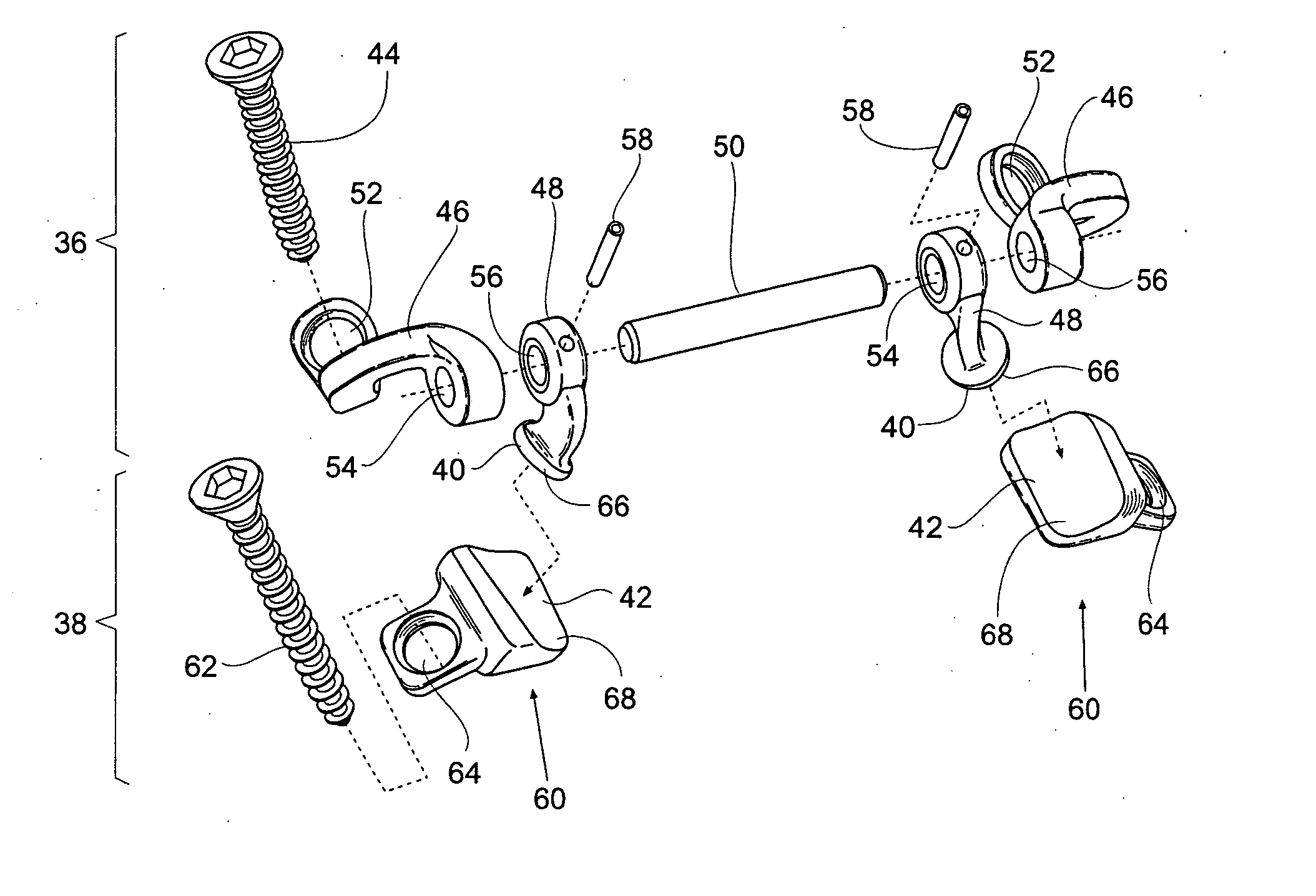
[0129] Similar to the previous embodiments, the cephalad prosthesis 154 is a modular unit comprising a fixation element 158, a support 160, and an arm 162 carrying an artificial facet joint structure 176 that allow assembly of the components in situ. A pair of fixation elements 158 (right and left) are desirably provided and sized and configured to be are secured to the right and left pedicles 16 in an orientation that provides secure fixation to bone. Components are mounted in situ on the fixation elements 158 that are secured to the pedicle 16 in an orientation that provides secure fixation to bone.

[0130] In the illustrated embodiment, each fixation element 158 takes the form of a sleeve 164 and a pedicle screw 166. The sleeve 164 is sized and configured for insertion into a bore 168 that has been reamed into the pedicle...


PUM

PropertyMeasurementUnit
Lengthaaaaaaaaaa
Widthaaaaaaaaaa
Symmetric field theoryaaaaaaaaaa

Abstract

Cephalad and caudal vertebral facet joint prostheses and methods of use are provided. A pair of fixation elements are adapted to be secured within a vertebra in an orientation that best assures a secure and durable attachment to cortical and/or cancellous bone. Artificial facet joint surfaces are mounted on the fixation elements, either directly or with the aid of a support. The artificial facet joint structure may be carried by an arm. The artificial facet joint structure is adapted for articulation with a complementary natural or artificial facet joint structure. Bilateral prostheses may by coupled by a brace to further secure and stabilize the prostheses.

Description

CROSS-REFERENCE [0001] This application is a continuation-in-part of U.S. patent application Ser. No. 10 / 158,563, filed May 30, 2002, and entitled “Prostheses, Systems and Methods for Replacement of Natural Facet Joints with Artificial Facet Joint Surfaces,” which is a continuation-in-part of U.S. patent application Ser. No. 10 / 067,137, filed Feb. 4, 2002, and entitled “Facet Arthroplasty Devices and Methods,” which is a continuation-in-part of U.S. patent application Ser. No. 09 / 693,272, filed Oct. 20, 2000, and entitled “Facet Arthroplasty Devices and Methods,” which claims the benefit of Provisional Patent Application Ser. No. 60 / 160,891, filed Oct. 22, 1999, and entitled “Facet Arthroplasty Devices and Methods,” all of which are incorporated herein by reference.FIELD OF THE INVENTION [0002] This invention relates to prostheses for treating various types of spinal pathologies, as well as to methods of treating spinal pathologies. BACKGROUND OF THE INVENTION I. Vertebral Anatomy ...

Claims


Application Information

Patent Timeline
IPC IPC(8): A61B17/16A61B17/86A61F2/00A61F2/02A61F2/28A61F2/30A61F2/44A61F2/46
CPCA61B17/1671A61F2310/00976A61B17/86A61F2/28A61F2/4405A61F2002/30331A61F2002/30332A61F2002/30387A61F2002/30433A61F2002/30471A61F2002/30492A61F2002/305A61F2002/30537A61F2002/30538A61F2002/3054A61F2002/30553A61F2002/30578A61F2002/30604A61F2002/30649A61F2002/30777A61F2002/30874A61F2002/30881A61F2002/30919A61F2002/449A61F2002/4631A61F2220/0025A61F2220/0033A61F2220/0041A61F2220/0091A61F2250/0004A61F2250/0006A61F2250/0008A61F2310/00017A61F2310/00023A61F2310/00029A61F2310/00131A61F2310/00179A61F2310/00329A61F2310/00604A61F2310/00634A61F2310/0097A61B17/7064A61F2002/30873
Inventor REILEY, MARK A.SCRIBNER, ROBERT M.JONES, LAWRENCE R.STINSON, DAVID
Owner GLOBUS MEDICAL INC
Why Eureka
Try Eureka