
Substrate holder for plasma processing

Inactive Publication Date: 2005-06-09
TOKYO ELECTRON LTD
View PDF10 Cites 21 Cited by
  • Summary
  • Abstract
  • Description
  • Claims
  • Application Information

AI Technical Summary

Benefits of technology

[0013] The present invention further describes a method of processing a substrate utilizing the improved substrate holder in order to minimize arcing between the edge of the

Problems solved by technology

One area of plasma processing in the semiconductor industry which presents formidable challenges is, for example, the manufacture of integrated circuits (ICs).
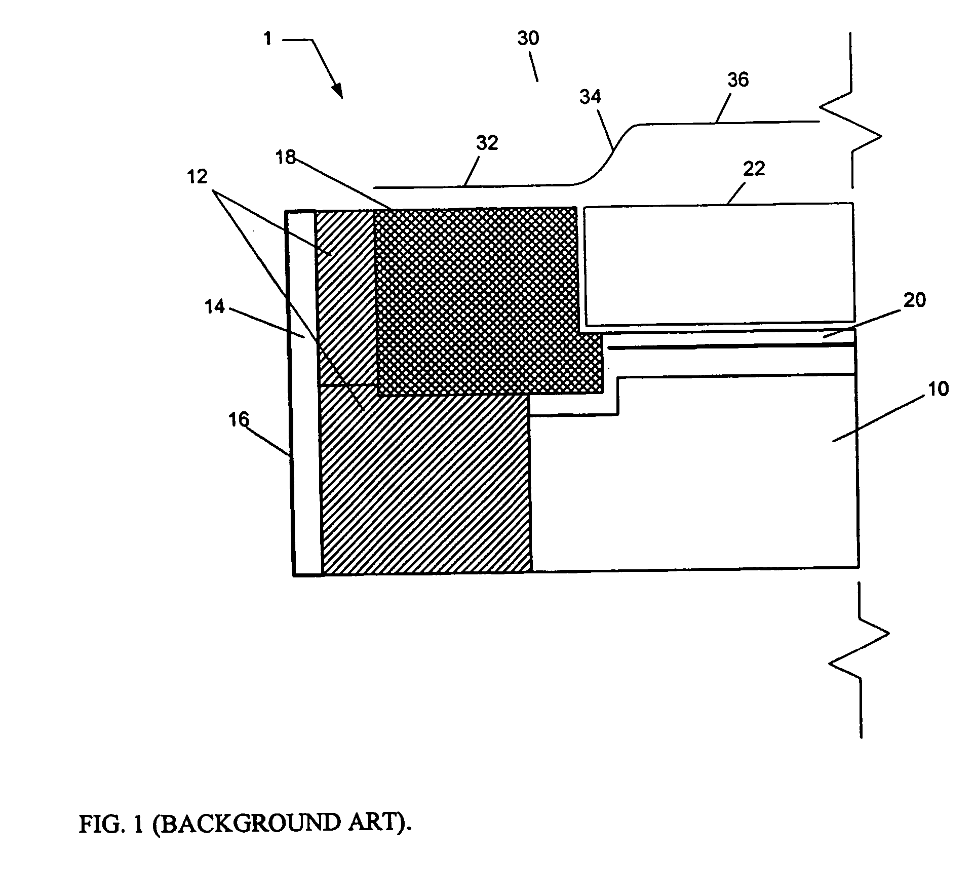
One such consequence of non-uniform plasma processing can be, for example, the unequal charging of the substrate surface in contact with the plasma and the focus ring surrounding the substrate.
Subsequently, the difference in surface potential can lead to a non-uniform plasma sheath thickness and, therefore, result in non-uniform plasma properties proximate the substrate edge.
Moreover, the difference in surface potential between the substrate edge and focus ring can be sufficiently great to cause an electrical discharge (arc) arising in a catastrophic process failure and reduced device yield.
As stated above, the potential difference associated with the non-uniform plasma sheath can manifest as substrate arcing, hence, leading to catastrophic reduction in device yield.
This observation is primarily attributable to the poor thermal contact between the focus ring and the temperature controlled electrode.
As a consequence, the “hot” focus ring can heat the substrate edge leading to non-uniform substrate temperatures and, hence, non-uniform substrate processing particularly local to the substrate edge.

Method used


Image

  • Substrate holder for plasma processing
  • Substrate holder for plasma processing
  • Substrate holder for plasma processing

Examples


Embodiment Construction

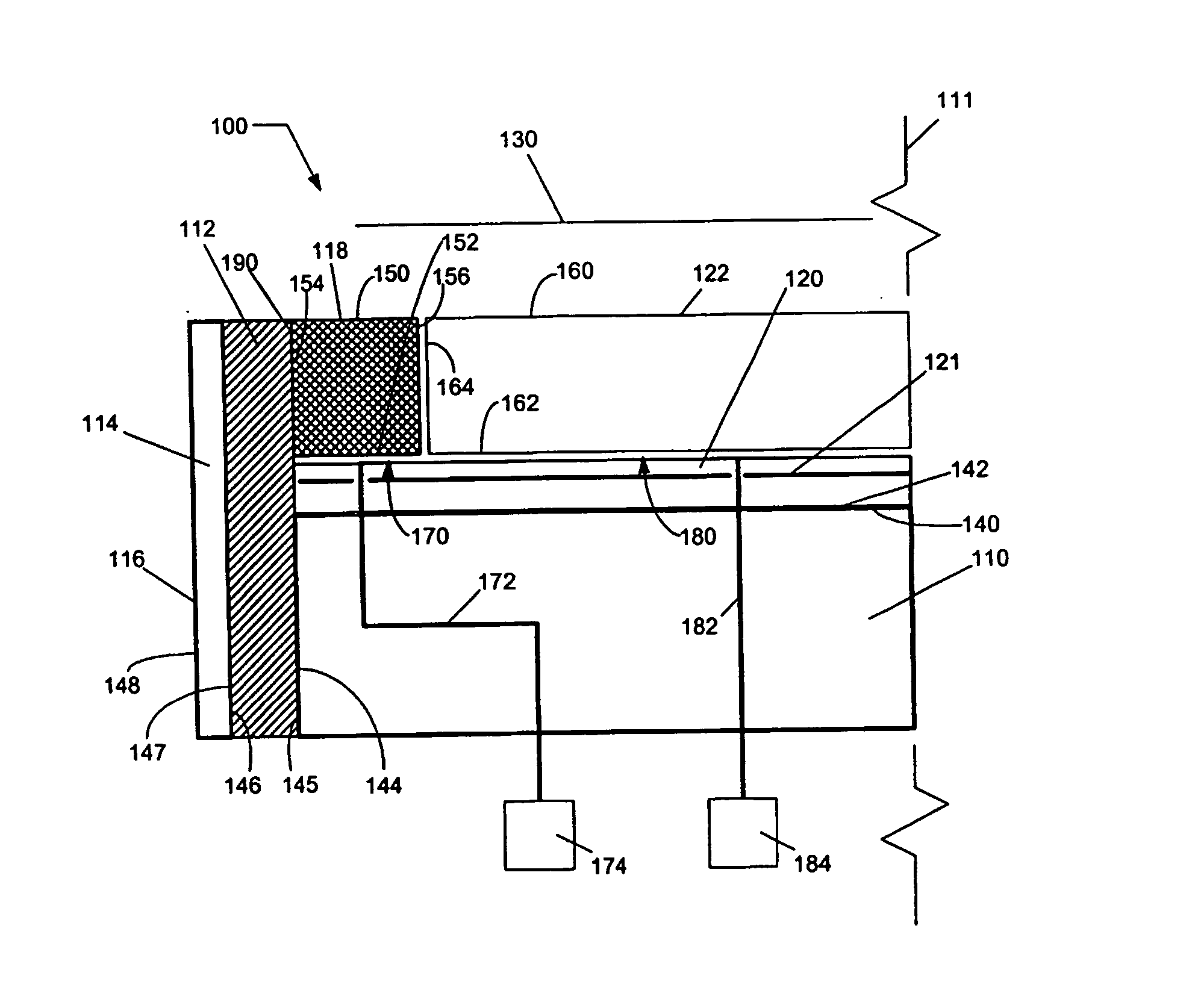
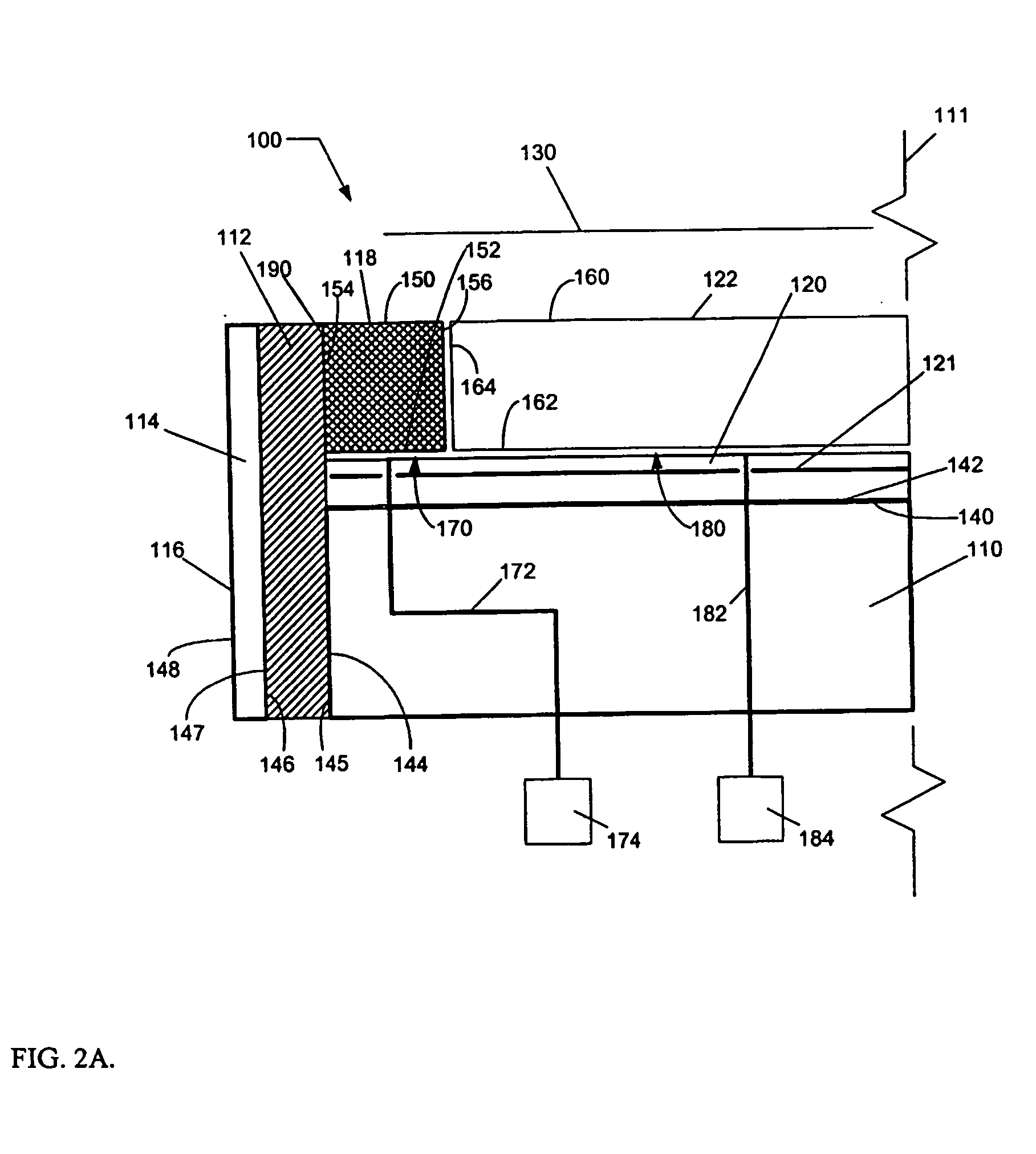
[0022] The present invention relates to a substrate holder employed in plasma processing and more particularly to an improved substrate holder for plasma processing. According to the illustrated embodiment of the present invention depicted in FIG. 2A, an improved substrate holder 100 can comprise an electrode 110, an insulating member 112 and a ground member 114. A focus ring 118, comprising an upper surface 150, a lower surface 152, an outer surface 154 at an outer diameter and an inner surface 156 at an inner diameter, is coupled to an upper surface 140 of electrode 110. The inner diameter of inner surface 156 of focus ring 118 is sufficiently large to accommodate substrate 122 and to center substrate 122 about an axis of revolution 111 of electrode 118. Substrate 122 comprises an upper surface 160, a bottom surface 162, and an outer surface 164 at an outer diameter facing inner surface 156 of focus ring 118. Substrate 122 is coupled to electrode 110 in such a way that bottom surf...


PUM

PropertyMeasurementUnit
Fractionaaaaaaaaaa
Fractionaaaaaaaaaa
Fractionaaaaaaaaaa

Abstract

An improved substrate holder comprises an electrode supporting a focus ring and a substrate, an insulating member surrounding the electrode and focus ring, a ground member surrounding the insulating member, and a focus ring surrounding the substrate. The focus ring provides a RF impedance substantially equivalent to a RF impedance of the substrate. A method of processing a substrate utilizing the improved substrate holder reduces arcing between the edge of the substrate and the focus ring. The method comprises the steps of placing the focus ring on the electrode, placing the substrate on the electrode and processing the substrate. Additionally, a method of controlling a focus ring temperature and a substrate temperature utilizing the improved substrate holder comprises the steps of placing the focus ring on the electrode, placing the substrate on the electrode, clamping the focus ring and the substrate to the electrode using an electrostatic clamp, supplying heat transfer gas(es) to the space residing between the focus ring and the electrode, and the space between the substrate and the electrode, and controlling the temperature of the electrode.

Description

CROSS-REFERENCE TO RELATED APPLICATIONS [0001] The present application claims priority and is related to U.S. application No. 60 / 363,284, filed on Mar. 12, 2002, the entire contents of which are herein incorporated by reference in their entirety.BACKGROUND OF THE INVENTION [0002] 1. Field of Invention [0003] The present invention relates to substrate holders employed in plasma processing and more particularly to an improved substrate holder for plasma processing. [0004] 2. Description of Related Art [0005] One area of plasma processing in the semiconductor industry which presents formidable challenges is, for example, the manufacture of integrated circuits (ICs). Demands for increasing the speed of ICs in general, and memory devices in particular, force semiconductor manufacturers to make devices smaller and smaller on the wafer surface. And conversely, while shrinking device sizes on the substrate is incurred, the number of devices fabricated on a single substrate is dramatically i...

Claims


Application Information

Patent Timeline
IPC IPC(8): H05H1/46C23C16/00H01J37/20H01L21/00H01L21/3065H01L21/31H01L21/683H01L21/687
CPCH01J37/20H01J37/32522H01J37/32642H01L21/68735H01L21/67069H01L21/67248H01L21/6831H01J2237/2001
Inventor CHEN, LEE
Owner TOKYO ELECTRON LTD
Learn More