Chassis frame buckling control device and chassis frame deformation control device

a control device and chassis frame technology, applied in the direction of shock absorbers, generators/motors, vehicular safety arrangments, etc., can solve the problems of chassis frame being unable to be made to buckle or deform at all times with respect to a plurality of different types of impacts, and achieve the effect of allowing for more precise control of chassis frame deformation

Inactive Publication Date: 2005-06-09
HONDA MOTOR CO LTD
View PDF5 Cites 16 Cited by
  • Summary
  • Abstract
  • Description
  • Claims
  • Application Information

AI Technical Summary

Benefits of technology

[0009] According to the chassis frame buckling control device, when a load in the direction of elongation is generated in the piezoelectric element actuator by the control of the control unit, the rigidity of the section of the frame where this piezoelectric element actuator is arranged increases as a result of the piezoelectric element actuator stretching, thereby resulting in greater resistance to buckling. Conversely, when a load in the direction of contraction is generated in the piezoelectric element actuator or when a load is not generated in the piezoelectric element actuator, the rigidity of the section of the frame where this piezoelectric element actuator is arranged decreases, thereby being able to promote buckling. Thus, the chassis frame can be made to buckle properly at all times with respect to a plurality of different types of impacts such as types of impacts in which resistance to buckling is preferable or types of impacts in which promotion of buckling is preferable.
[0011] In this case, since the piezoelectric element actuator is provided in the vicinity of a weak section of the chassis frame, when a load in the direction of elongation is generated in the piezoelectric element actuator by the control of the control unit, the rigidity of the section of the chassis frame where the piezoelectric element actuator is arranged increases as a result of the piezoelectric element actuator stretching, thereby making it possible to increase the resistance to buckling even if there is a weak section nearby. Conversely, when a load in the direction of contraction is generated in the piezoelectric element actuator or a load is not generated in the piezoelectric element actuator, the rigidity of the section of the chassis frame where the piezoelectric element actuator is arranged decreases, thereby making it possible to promote buckling starting from the weak section nearby.
[0016] In this case, since the location of the chassis frame where buckling progresses can be detected with the detection unit, and the generation of the load in the piezoelectric element actuator can be controlled corresponding to the detection results, namely the location where buckling progresses, deformation of the chassis frame can be controlled more precisely. For example, buckling can be made to occur farther towards the rear from the bent section by generating a load in the direction of elongation in the piezoelectric element actuator during an impact causing it to stretch, allowing that buckling to reach the bent section, and discontinuing stretching by removing the load of the piezoelectric element actuator when buckling reaches the bent section. In other words, in cases when collapse and buckling are desired, the chassis frame can be made to collapse and buckle reliably even if there are bent sections.

Problems solved by technology

As was previously stated, in the case of passive buckling control in which an indentation is provided in a chassis frame, since the buckling starting load and other deformation load characteristics have only one specification, there was the problem of the chassis frame being unable to be made to properly buckle or deform at all times with respect to a plurality of different types of impacts.

Method used


Image

  • Chassis frame buckling control device and chassis frame deformation control device
  • Chassis frame buckling control device and chassis frame deformation control device
  • Chassis frame buckling control device and chassis frame deformation control device

Examples


first embodiment

[0029] The following provides an explanation of a chassis frame buckling control device of a first embodiment of the present invention with reference to the drawings.

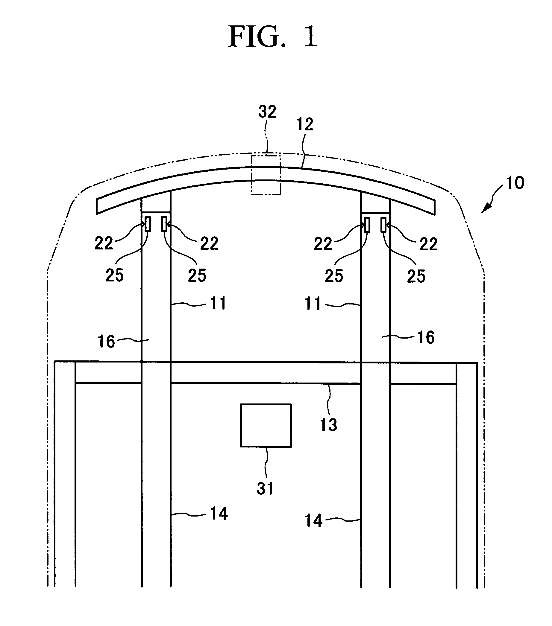
[0030]FIG. 1 shows the front section of a chassis of a vehicle 10. In the front section of chassis, a pair of front side frames (chassis frames) 11, which are chassis frame members, are provided separated in the direction of vehicle width in the state of running in the longitudinal direction of the chassis. The distal ends of the front side frames 11 are respectively coupled to a front bumper beam 12 that extends in the direction of vehicle width. The proximal ends of the front side frames 11 respectively intersect with a dashboard lower cross member 13 extending in the direction of vehicle width, and are coupled to floor frames 14 that extend in the longitudinal direction of the chassis.

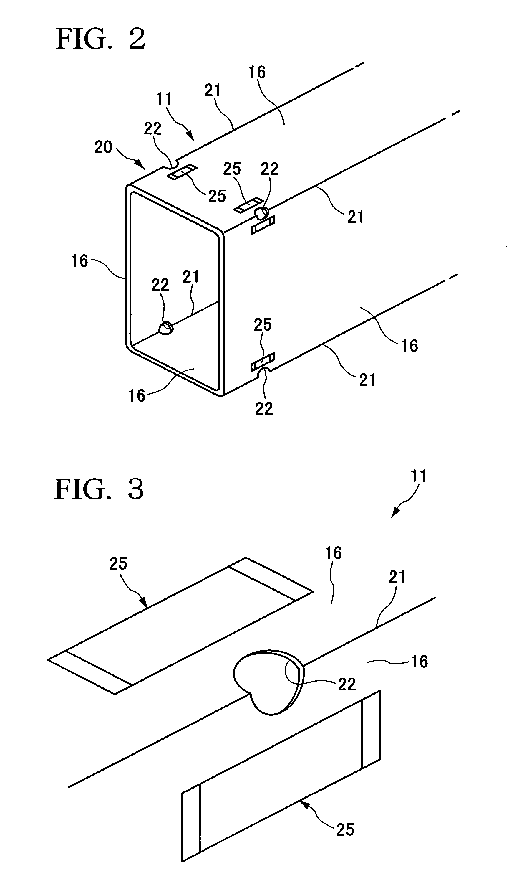
[0031] The front side frames 11 are made of a steel material, and as schematically shown in FIG. 2, four plate sections 16 are coupl...

second embodiment

[0043] The following provides an explanation of a chassis frame deformation control device of a second embodiment of the present invention with reference to the drawings.

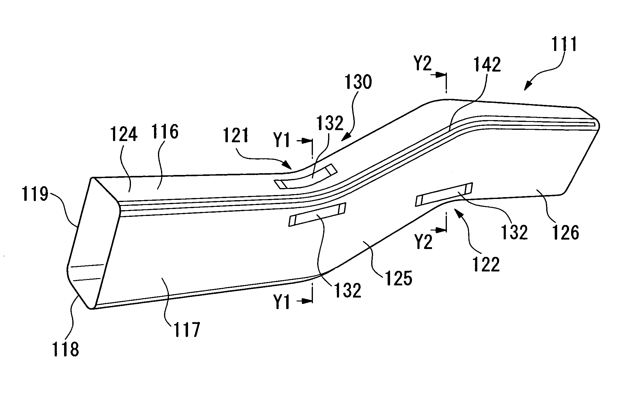
[0044]FIG. 6 shows the front section of a chassis of a vehicle 110. In the front section of the chassis, a pair of front side frames (chassis frames) 111, which are chassis frame members, are provided separated in the direction of vehicle width in the state of running in the longitudinal direction of the chassis. The distal ends of the front side frames 111 are respectively coupled to a front bumper beam 112 that extends in the direction of vehicle width. The proximal ends of the front side frames 111 respectively intersect with a dashboard lower cross member 113 extending in the direction of vehicle width, and are coupled to floor frames 114 that extend in the longitudinal direction of the chassis.

[0045] The front side frames 111 are made of a steel material, and as schematically shown in FIG. 7, FIG. 8A and FIG....


PUM


Abstract

The present invention is including: a piezoelectric element actuator provided on a chassis frame and capable of generating a load along the chassis frame; and, a control unit that controls the load of the piezoelectric element actuator.

Description

BACKGROUND OF THE INVENTION [0001] 1. Field of the Invention [0002] The present invention relates to a chassis frame buckling control device and a chassis frame deformation control device that control collapse buckling and deformation of a chassis frame that occur during an impact. [0003] The present application claims priority on Japanese Patent Application No. 2003-404377 filed on Dec. 3, 2003, and Japanese Patent Application No. 2003-404378 filed on Dec. 3, 2003, the contents of which are incorporated herein by reference. [0004] 2. Description of the Related Art [0005] Technology has been disclosed wherein, by providing an indentation referred to as a bead in the leading edge of a front frame that is a member of a chassis, buckling is controlled so that the front frame buckles starting from the indentation in the case a compressive load is applied to the front frame (refer to, for example, Japanese Unexamined Patent Application, First Publication No. H07-165110). [0006] As was pr...

Claims


Application Information

Patent Timeline
Patent Type & Authority Applications(United States)
IPC IPC(8): B60R19/00B62D21/15H01L41/08H01L41/09
CPCB60R2019/007B62D21/15F16F2224/0283H01L41/0986H01L41/0471H10N30/871H10N30/206
Inventor MAE, HIROYUKI
Owner HONDA MOTOR CO LTD
Why Eureka
Try Eureka