

Plasma display panel
a plasma display and plasma technology, applied in the direction of gas discharge electrodes, gas-filled discharge tubes, electrodes, etc., can solve the problems of prone to breakage, reduced pdp yield, and generation of line defects, so as to improve discharge efficiency and plasma discharge the effect of large area
- Summary
- Abstract
- Description
- Claims
- Application Information
AI Technical Summary
Benefits of technology
Problems solved by technology
Method used
Image

Examples
first embodiment
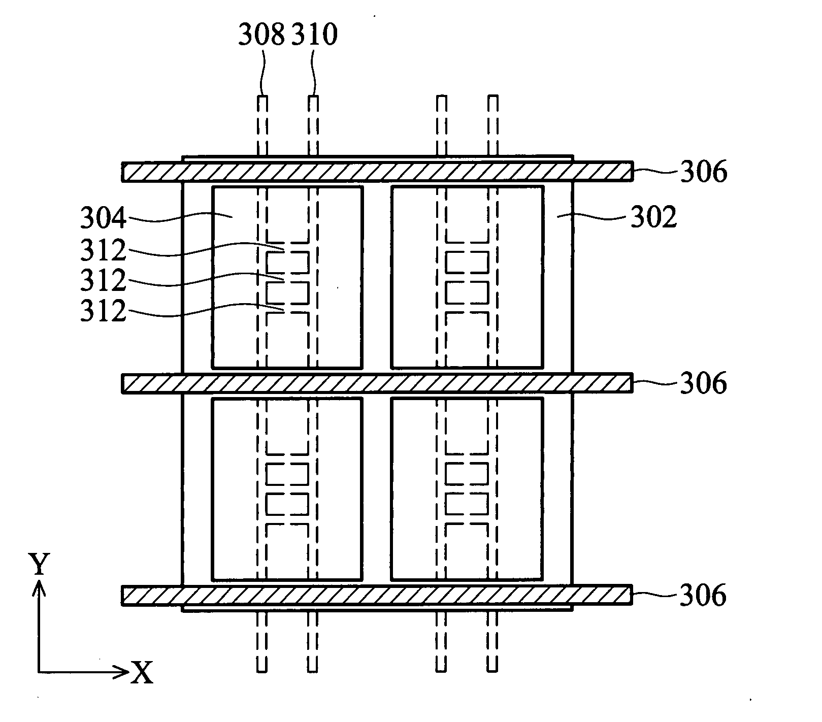
[0026]FIGS. 3A and 3B are top views of the PDP of the first embodiment. A PDP comprises a front substrate and a rear substrate. Referring to FIG. 3A, a plurality of ribs 302 are formed on the rear substrate, defining a plurality of closed rectangular discharge cells 304. The front and rear substrates are preferably glass.
[0027] A plurality of row electrodes 306 are formed on the front substrate, extending in the direction X along the horizontal side of the rectangular ribs 302. A plurality of fence shaped address electrodes are formed on the rear substrate, and each closed rectangular cell 304 passes trough a fence shaped address electrode, each of which comprises a plurality of main electrodes and at least one auxiliary electrode in each cell. In FIG. 3A, the main electrodes are referred to as a first main electrode 308 and a second main electrode 310. At least one auxiliary electrode 312 is interposed between the first main electrode 308 and the second main electrode 310, providi...
second embodiment
[0028]FIG. 4 is top view of the PDP of a second embodiment of the invention. A PDP comprises a front substrate and a rear substrate. Referring to FIG. 4, a plurality of ribs 402 are formed on the rear substrate, defining a plurality of closed hexagonal discharge cells 404. The front and rear substrates are preferably glass.
[0029] The hexagonal discharge cells 404 are arranged in delta configurations. A plurality of row electrodes 406 are formed on the front substrate, extending substantially in the direction X along the bevel side of the hexagonal ribs 402. A plurality of fence shaped address electrodes are formed on the rear substrate, and each closed hexagonal cell 404 pass trough a fence shaped address electrode, wherein each of which comprises a plurality of main electrodes and at least one auxiliary electrode. In FIG. 4, the main electrodes are referred to as a first main electrode 408 and a second main electrode 410, in which the first and second main electrodes are zigzag sh...
third embodiment
[0031]FIG. 5 is top view of the PDP of the third embodiment of the invention. A PDP comprises a front substrate and a rear substrate. Referring to FIG. 5, a plurality of line shaped ribs 502 are formed on the rear substrate, extending in the direction Y. The front and rear substrates are preferably glass.
[0032] A plurality of row electrodes 506 are formed on the front substrate, extending in the direction X. The line shaped ribs 502 and the row electrodes 506 define a plurality of discharge cells 504. A plurality of fence shaped address electrodes are formed on the rear substrate, and each rectangular cell passes trough a fence shaped address electrode, each of which comprises a plurality of main electrodes and at least one auxiliary electrodes. In FIG. 5, the main electrodes are referred to as a first main electrode 508 and a second main electrode 510. At least one auxiliary electrode 512 is interposed between the first and the second main electrode 508 and 510, providing electric...
PUM
 Abstract
Description
Claims
Application Information