
Electro-optic displays, and methods for driving same

a technology of electrooptic displays and driver connections, applied in the field of large-area electrooptic displays, can solve the problems of inadequate service life of these displays, unable to meet the needs of users, and gas-based electrophoretic media are susceptible to the same types of problems, so as to achieve the effect of relatively small overall cost of providing driver connections for every pixel

Active Publication Date: 2005-06-09
E INK CORPORATION
View PDF99 Cites 276 Cited by
  • Summary
  • Abstract
  • Description
  • Claims
  • Application Information

AI Technical Summary

Benefits of technology

[0058] The DMDD is primarily intended for use with electro-optic displays, including any of the types of electro-optic media discussed above. The DMDD may be particularly useful in displays of the direct drive type mentioned above, which are divided into a series of pixels each of which is provided with a separate electrode, the display further comprising switching means arranged to control independently the voltage applied to each separate electrode. The DMDD may also be useful for in large-area direct-driven matrix displays where the overall cost of providing driver connections for every pixel is relatively small compared to other costs, such as the costs of the electro-optic medium.
[0059] This invention also provides a display assembly (the “DMDD assembly” of the present invention) comprising a plurality of display modules each of which has a display module driver device of the present invention associated therewith and arranged to control the image displayed on its associated display module, and display assembly input means arranged to receive image data representing images to be displayed on the display assembly and to provide at least part of the image data to each display module driver device.

Problems solved by technology

Nevertheless, problems with the long-term image quality of these displays have prevented their widespread usage.
For example, particles that make up electrophoretic displays tend to settle, resulting in inadequate service-life for these displays.
Such gas-based electrophoretic media appear to be susceptible to the same types of problems due to particle settling as liquid-based electrophoretic media, when the media are used in an orientation which permits such settling, for example in a sign where the medium is disposed in a vertical plane.
Indeed, particle settling appears to be a more serious problem in gas-based electrophoretic media than in liquid-based ones, since the lower viscosity of gaseous suspending fluids as compared with liquid ones allows more rapid settling of the electrophoretic particles.
Furthermore, it has now been found, at least in the case of many particle-based electro-optic displays, that the impulses necessary to change a given pixel through equal changes in gray level (as judged by eye or by standard optical instruments) are not necessarily constant, nor are they necessarily commutative.
Although these problems can be reduced or overcome by driving all pixels of the display to one of the extreme states for a substantial period before driving the required pixels to other states, the resultant “flash” of solid color is often unacceptable; for example, a reader of an electronic book may desire the text of the book to scroll down the screen, and may be distracted, or lose his place, if the display is required to flash solid black or white at frequent intervals.
Furthermore, such flashing of the display increases its energy consumption and may reduce the working lifetime of the display.
When an active matrix electro-optic display is being rewritten (i.e., when a new image is being placed upon the display, or an image is being refreshed), the charging and discharging of the column electrodes can be a significant source of power consumption.
Such a large area display can be heavy and expensive, and can be significantly limited in its scalability to larger sizes.
However, one of the challenges in the construction of such large-area signs is the design of the drive electronics.
As explained above, the drive requirements of electro-optic media typically render known drivers designed for driving liquid crystal displays unsuitable for use in driving bistable electro-optic displays without custom modification.
Such data loading may take a significant amount of time.
Also, because data is typically transmitted at a relatively high frequency, the data path may be unnecessarily fragile, potentially resulting in data corruption.

Method used


Image

  • Electro-optic displays, and methods for driving same
  • Electro-optic displays, and methods for driving same
  • Electro-optic displays, and methods for driving same

Examples


Embodiment Construction

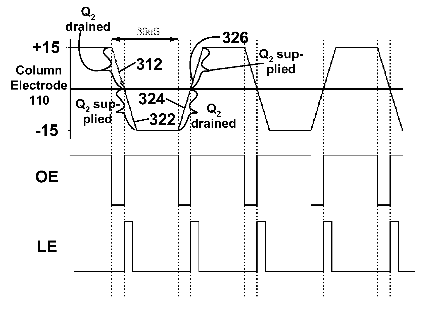
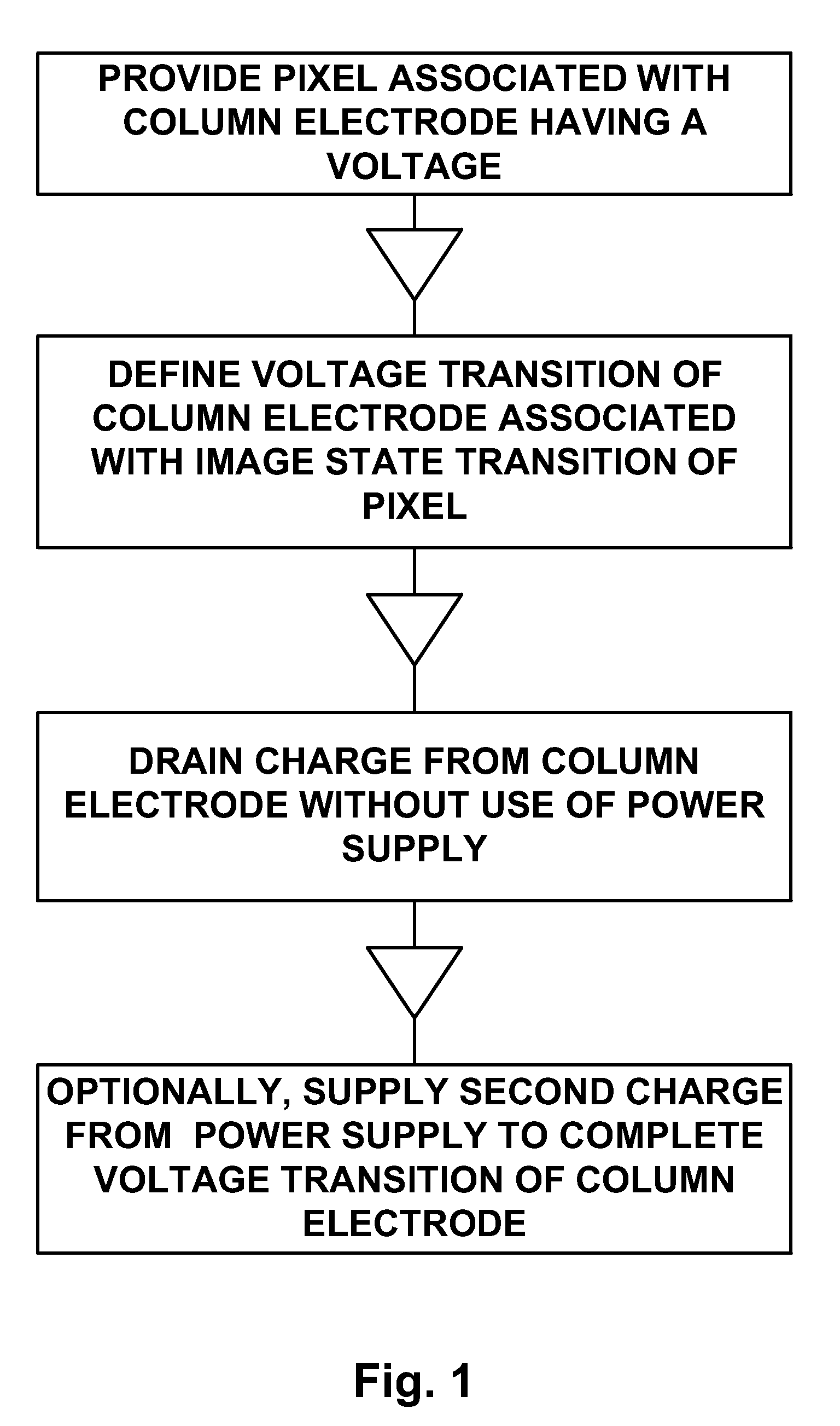
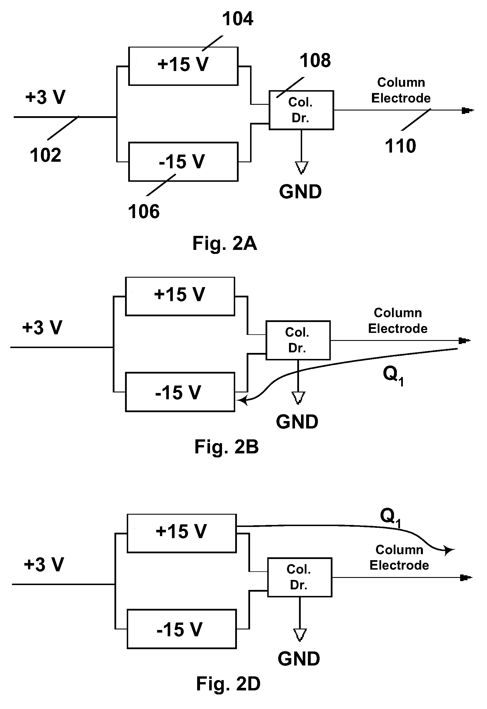
[0081] As already mentioned, the present invention has three main aspects, namely (a) two-step voltage change methods, and apparatus for carrying out such methods; (b) flexible large area displays; and (c) display module driver devices, and display assemblies containing such devices. These various aspects of the present invention will be described separately below, although it should be understood that a single display or driving method therefore may make use of more than one aspect of the present invention. For example, a DMDD assembly of the invention might effect a two-step voltage change method of the invention and might be used to drive a flexible large area display of the invention.

[0082] Two-Step Voltage Change Methods, and Apparatus for Carrying Out Such Methods

[0083] As already mentioned, this invention provides a method two-step voltage change method (TSVCM) for driving an electro-optic display having an electro-optic medium, a pixel electrode capable of applying an elec...


PUM

PropertyMeasurementUnit
voltageaaaaaaaaaa
column capacitanceaaaaaaaaaa
chargeaaaaaaaaaa

Abstract

An electro-optic display includes an electro-optic medium, a pixel electrode for applying an electric field to the medium and a column electrode associated with the pixel electrode. To reduce power consumption, when it is necessary to change the voltage on the column electrode from a first value to a second value to change the optical state of the electro-optic medium, the column electrode voltage is first changed to a third value intermediate the first and second values to permit charge to flow to or from the column electrode, and thereafter the column electrode voltage is changed from the third voltage to the second voltage.

Description

REFERENCE TO RELATED APPLICATIONS [0001] This application claims benefit of Application Ser. No. 60 / 525,023, filed Nov. 25, 2003, and of Application Ser. Nos. 60 / 525,870 and 60 / 525,888, both filed Dec. 8, 2003. [0002] This application is related to copending application Ser. No. 10 / 879,335, filed Jun. 29, 2004, which itself is a continuation-in-part of copending application Ser. No. 10 / 814,205, filed Mar. 31, 2004, which itself is a continuation-in-part of copending application Ser. No. 10 / 065,795, filed Nov. 20, 2002 (Publication No. 2003 / 0137521). The aforementioned application Ser. No. 10 / 879,335 claims benefit of Application Ser. No. 60 / 481,040, filed Jun. 30, 2003, of Application Ser. No. 60 / 481,053, filed Jul. 2, 2003, and of Application Ser. No. 60 / 481,405, filed Sep. 22, 2003. The aforementioned application Ser. No. 10 / 814,205 claims benefit of Application Ser. No. 60 / 320,070, filed Mar. 31, 2003, of Application Ser. No. 60 / 320,217, filed May 5, 2003, of Application Ser. No....

Claims


Application Information

Patent Timeline
Patent Type & Authority Applications(United States)
IPC IPC(8): G02B
CPCG09G2330/021G09G2340/16G09G2320/041G09G3/344G06F3/1446G09G2300/026G09G3/3453G09G2310/0275Y10T29/4913G02F1/133305G02F1/133308G02F1/13336G02F2202/28G02F1/133311
Inventor GATES, HOLLY G.ZEHNER, ROBERT W.ALBERT, JONATHAN D.
Owner E INK CORPORATION
Features
  • Generate Ideas
  • Intellectual Property
  • Life Sciences
  • Materials
  • Tech Scout
  • Unparalleled Data Quality
  • Higher Quality Content
  • 60% Fewer Hallucinations
Learn More