Line thermal head printer device

a printer device and thermal head technology, applied in typewriters, printing, instruments, etc., can solve the problems of large size and considerable space, and achieve the effect of remarkably small printer device siz

Inactive Publication Date: 2005-06-09
DAISEY MASCH CO LTD
View PDF6 Cites 2 Cited by
  • Summary
  • Abstract
  • Description
  • Claims
  • Application Information

AI Technical Summary

Benefits of technology

[0016] It is therefore an object of the present invention to provide a line thermal head printer device in which parts and components thereof are arranged differently from the prior art line thermal head printer device so that the size of the printer device can be made remarkably smaller.
[0022] According to the line thermal head printer device of the present invention mentioned in (1) above, the stepping motor and the line thermal head are arranged on one side portion of the frame plate and on one side of them on the frame plate, the ribbon tape unwinding drive shaft and the ribbon tape winding drive shaft are arranged so that the line connecting the stepping motor and the line thermal head inclinedly crosses with the line connecting the ribbon tape unwinding drive shaft and the ribbon tape winding drive shaft. Thereby, the parts and components constituting the line thermal head printer device are efficiently arranged without an unused space on the flat surface of the frame plate usually of a square or rectangular shape. Also, the ribbon tape fed between each of the reels supported to both of the drive shafts are led to run around these parts and components, that is, along the periphery of the frame plate. Thereby, the surface of the frame plate is effectively used and the construction of the parts and components can be made further compact.
[0025] According to the line thermal head printer device of the present invention mentioned in (4) above, the ribbon tape unwinding drive shaft is arranged on one side of the line thermal head and the ribbon tape winding drive shaft is arranged on one side of the stepping motor. Thereby, the space on the frame plate can be efficiently used for leading the ribbon tape.

Problems solved by technology

Thus, in the prior art line thermal head printer devices of both of the fixed head type and the movable head type, there is a problem that the size is large and a considerable space is needed for fitting the printer device to the surrounding apparatus and hence the printer device is currently desired to be made further smaller.

Method used


Image

  • Line thermal head printer device
  • Line thermal head printer device
  • Line thermal head printer device

Examples


first embodiment

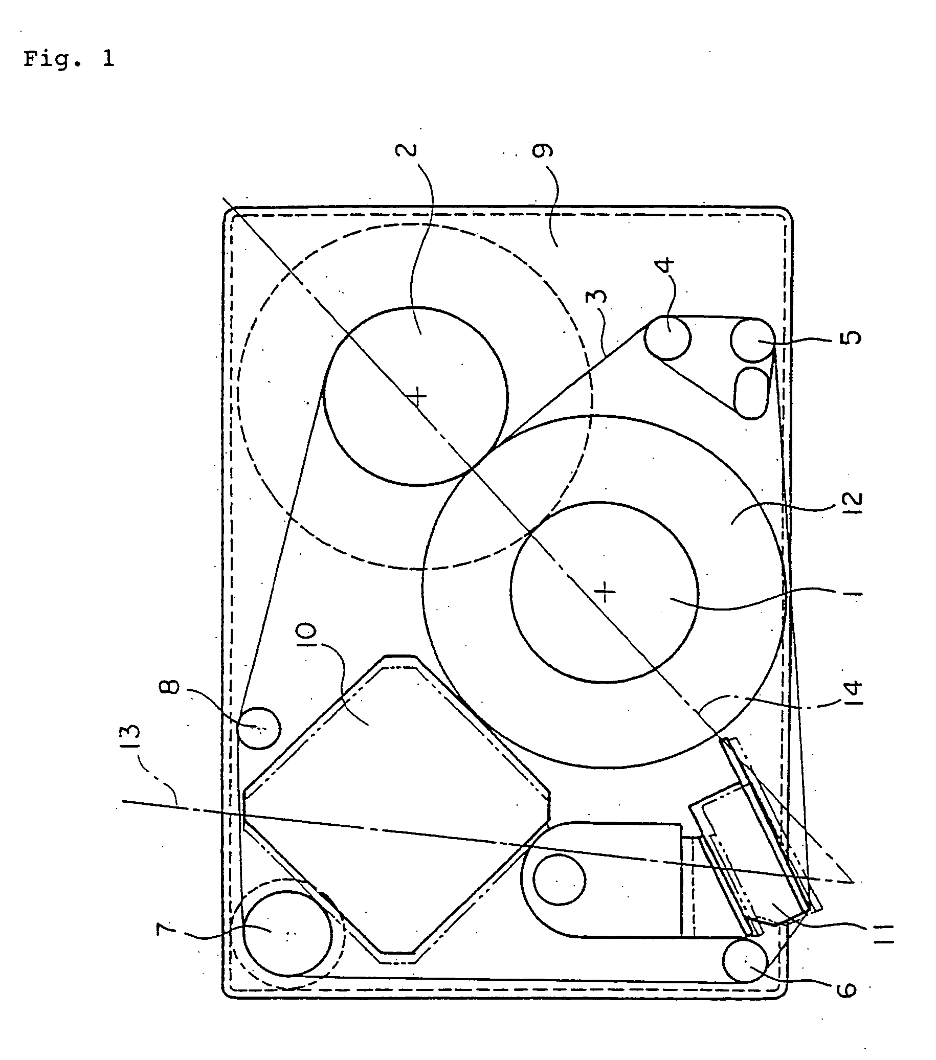
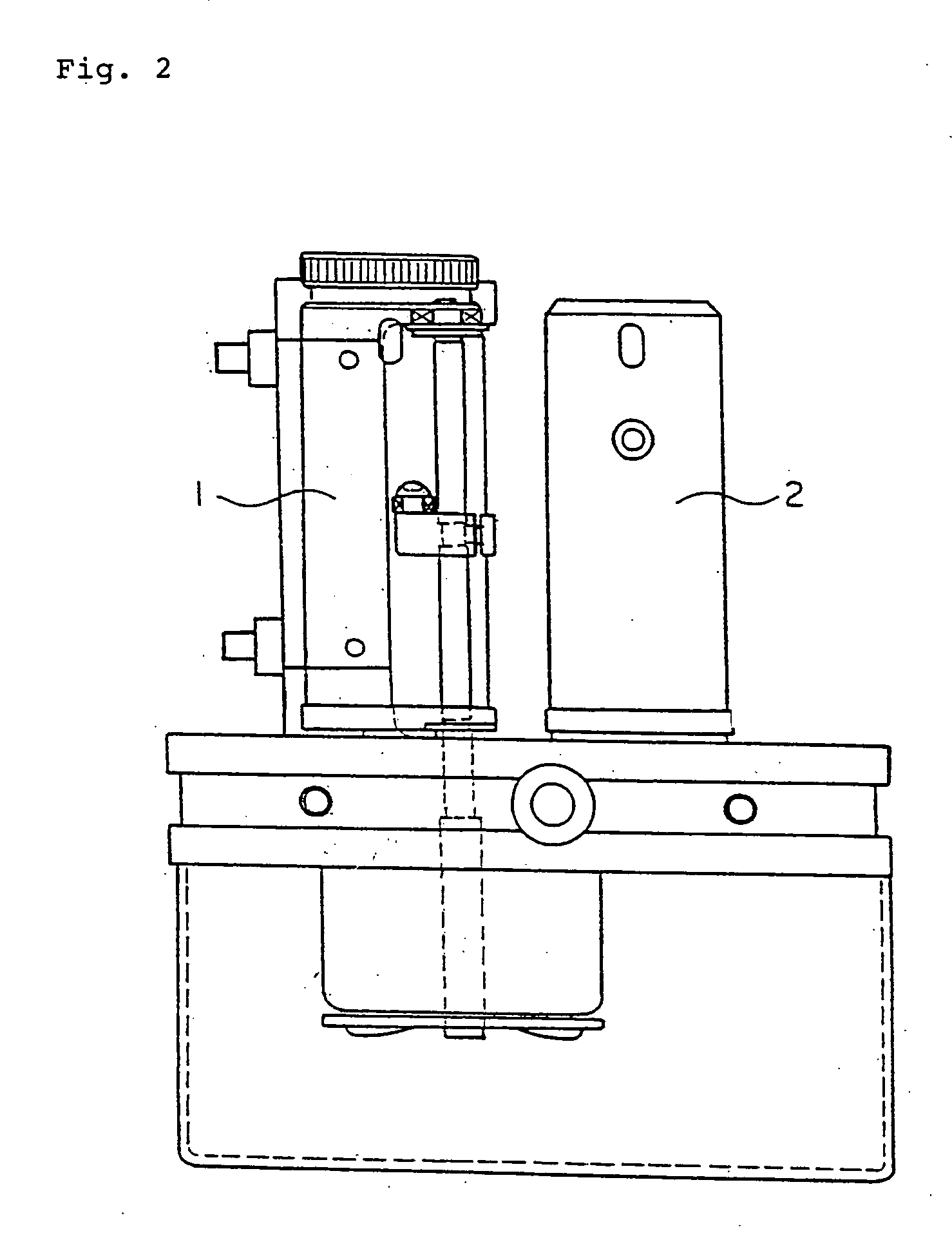
[0034]FIG. 1 is a plan view and FIG. 2 is a right-hand side view, that is, a side view seen from the right-hand side of FIG. 1, both of a line thermal head printer device of a first embodiment according to the present invention. This first embodiment is an example where the present invention is applied to a printer device having a fixed type line thermal head. In FIGS. 1 and 2, numeral 1 designates a ribbon tape unwinding drive shaft and numeral 2 a ribbon tape winding drive shaft. The ribbon tape unwinding drive shaft 1 is arranged on one side of a line thermal head 11 to be described later. The ribbon tape winding drive shaft 2 is arranged on an upper corner portion on the right-hand side of FIG. 1. On the left-hand side upper corner portion opposite to the ribbon tape winding drive shaft 2, a stepping motor 10, to be described later, is arranged.

[0035] A ribbon tape unwinding reel of a ribbon tape master roll 12 is fitted to the ribbon tape unwinding drive shaft 1 so that the ri...

second embodiment

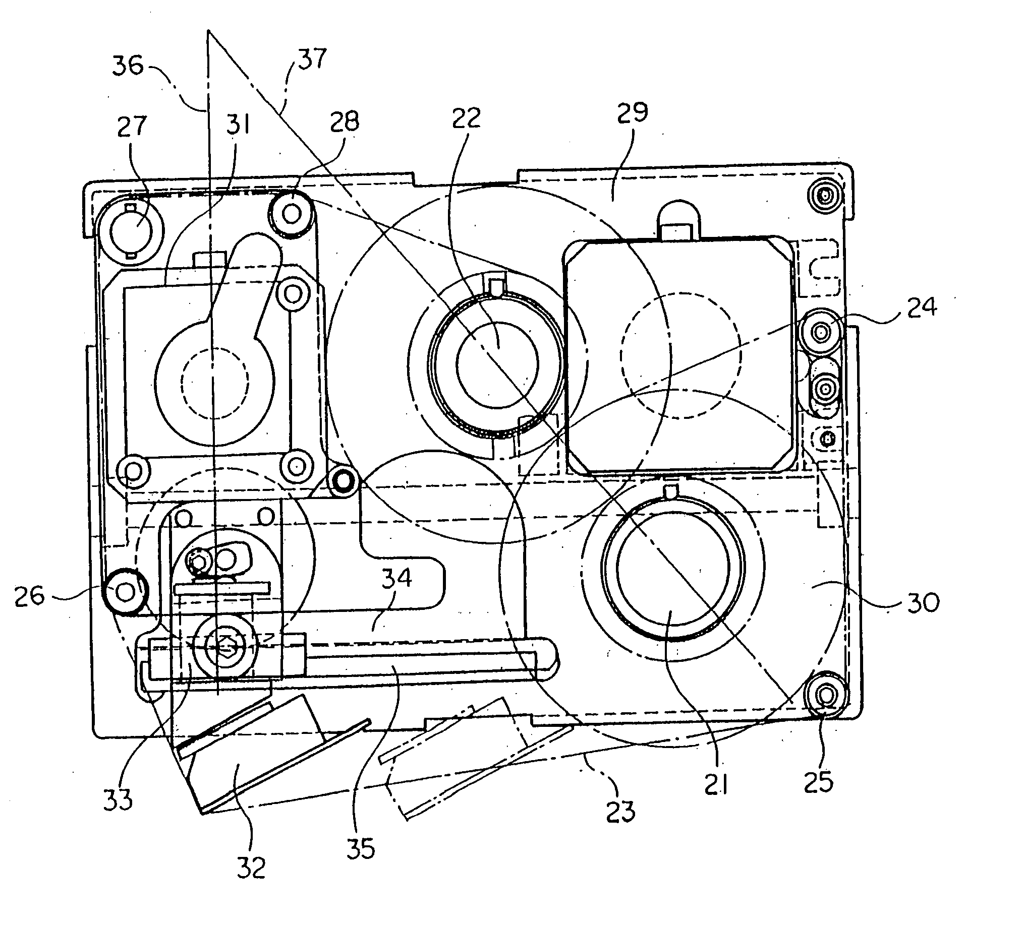
[0042]FIG. 3 is a plan view and FIG. 4 is a right-hand side view, that is, a side view seen from the right-hand side of FIG. 3, both of a line thermal head printer device of a second embodiment according to the present invention. This second embodiment is an example where the present invention is applied to a printer device having a movable type line thermal head. In FIGS. 3 and 4, numeral 21 designates a ribbon tape unwinding drive shaft and numeral 22 a ribbon tape winding drive shaft. The ribbon tape unwinding drive shaft 21 is arranged on the right-hand side lower corner portion of FIG. 3. On the left-hand side lower corner portion opposite to the ribbon tape unwinding drive shaft 21, a line thermal head 32, to be described later, is arranged. The ribbon tape winding drive shaft 22 is arranged on the upper central portion of FIG. 3 and, on the left-hand side upper corner portion adjacent to the ribbon tape winding drive shaft 22, a stepping motor 31, to be described later, is ar...


PUM


Abstract

A line thermal head printer device of which size is made remarkably smaller is provided. A stepping motor (10) rotationally driving a ribbon tape reel is arranged to be fitted to one corner portion of a frame plate (9). A line thermal head (11) is arranged to be fitted to a corner portion of the frame plate (9) adjacent to this one corner portion. A ribbon tape winding drive shaft (2) and a ribbon tape unwinding drive shaft (1) are arranged on one side of the stepping motor (10) and the line thermal head (11), respectively, to be fitted to the frame plate (9). By this arrangement, parts and components are efficiently arranged without unused space on a surface of the frame plate (9) of a square or rectangular shape. Also, a ribbon tape (3) fed between reels fitted to the drive shafts (1, 2) is led around the parts and components, that is, along a periphery of the frame plate (9). Thereby, the parts and components are effectively arranged on the surface of the frame plate (9) and the construction can be made remarkably smaller.

Description

BACKGROUND OF THE INVENTION [0001] 1. Field of the Invention [0002] The present invention relates to a printer device, especially a compactly made printer device, that performs printing of letters and marks on a print object sheet by using a hot release type thermal transfer ribbon tape and a line thermal head. [0003] 2. Description of the Prior Art [0004] In recent years, as an information of packaged goods indicated on a packaging material, there are often cases where letters and marks, such as date of manufacture, tastable time period, series number of manufacture, etc. are printed differently for each object sheet to be printed (herein referred to as a print object sheet). In such cases, the printing is often done by using a hot release type thermal transfer ribbon tape and a line thermal head. [0005] As the printing is carried out in the manufacturing process of the packaged goods, that is, for example, in the process to package the goods, the printer device used therefor is re...

Claims


Application Information

Patent Timeline
Patent Type & Authority Applications(United States)
IPC IPC(8): B41J3/407B41J2/325B41J17/02
CPCB41J3/407
Inventor SOGABE, MASUO
Owner DAISEY MASCH CO LTD
Why Eureka
Try Eureka