Magnetic tape cartridge, servo writer, magnetic tape drive and method for reading servo signal

Inactive Publication Date: 2005-06-09
FUJIFILM HLDG CORP +1
View PDF18 Cites 17 Cited by
  • Summary
  • Abstract
  • Description
  • Claims
  • Application Information

AI Technical Summary

Benefits of technology

[0049] According to the sixth aspect, the servo signal that has been written on the magnetic tape in the magnetic tape cartridge is read in the servo signal reading process. Following this, the servo signal is decoded in the servo signal decoding process, and the output level data is extracted from the servo signal. Subsequently, the output level of the servo signal is corrected based on th

Problems solved by technology

Such a high density recording design involves excessive narrowing of the data tracks and of the intervals between the adjacent data tracks in a magnetic tape.
Consequently, a magnetic tape drive fails to read the servo signal SS correctly, and to exactly control the position of the magnetic head.
Upon occ

Method used


Image

  • Magnetic tape cartridge, servo writer, magnetic tape drive and method for reading servo signal
  • Magnetic tape cartridge, servo writer, magnetic tape drive and method for reading servo signal
  • Magnetic tape cartridge, servo writer, magnetic tape drive and method for reading servo signal

Examples


first embodiment

[0076] Description will be given in detail below of a magnetic tape cartridge, a servo writer, a magnetic tape drive, and a method for reading a servo signal, which are all according to a first embodiment of the present invention, with reference to accompanying figures as appropriate.

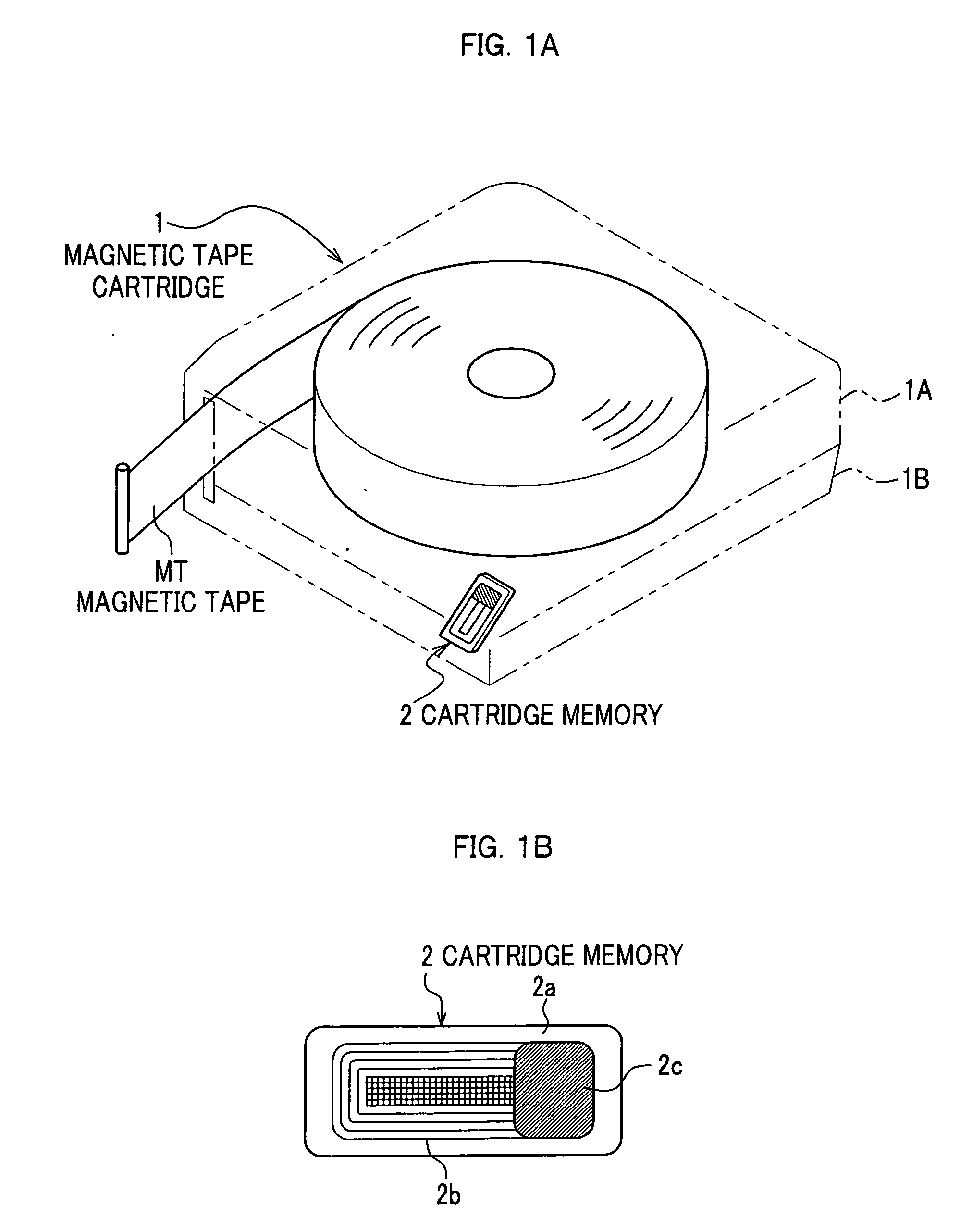
[0077] As FIGS. 1A and 1B, a magnetic tape cartridge 1 includes, as main components, upper and lower cases 1A and 1B split apart from each other, a magnetic tape MT on which data is to be recorded and which is placed inside the upper and lower cases 1A and 1B, and a cartridge memory 2 which communicates information in a non-contact manner. The cartridge memory 2 is a rectangular, thin electric component, and includes an IC chip (not shown) within as a main element, a glob top 2c that is formed of a resin as a sealant and that seals the IC chip, a substrate 2a, and a loop antenna 2b that is printed on the substrate 2a and that is connected to the loop antenna 2b.

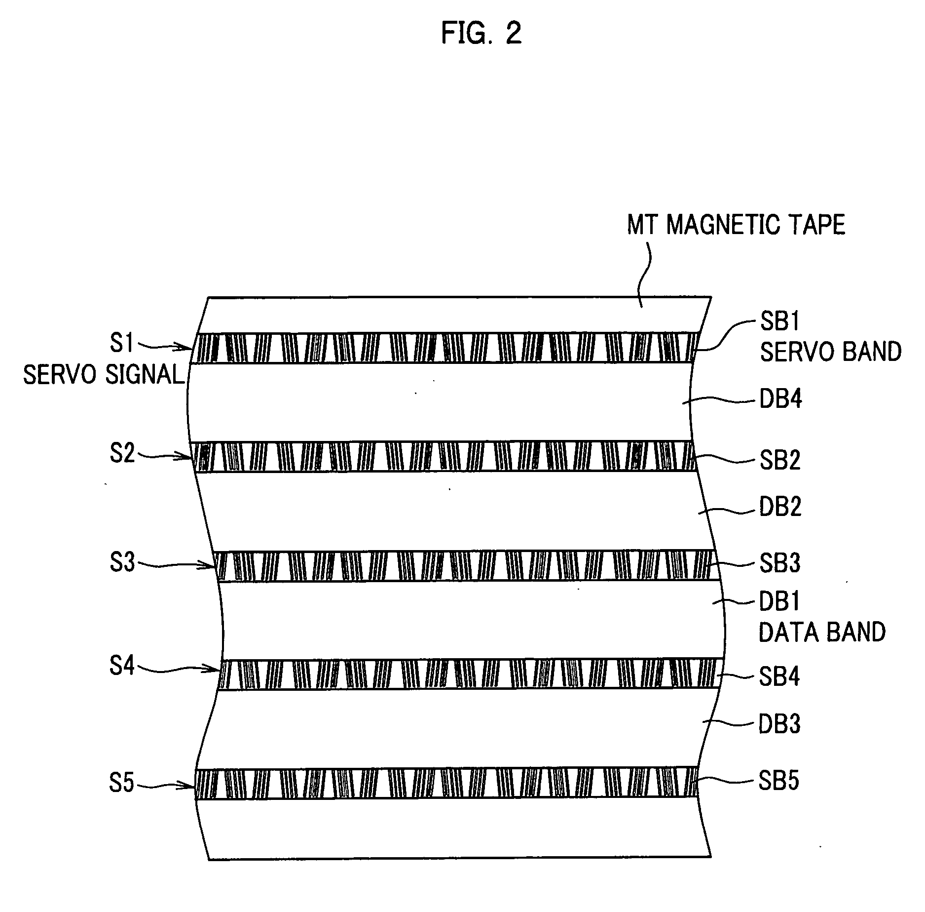
[0078] With reference to FIGS. 2 and 3, ...

second embodiment

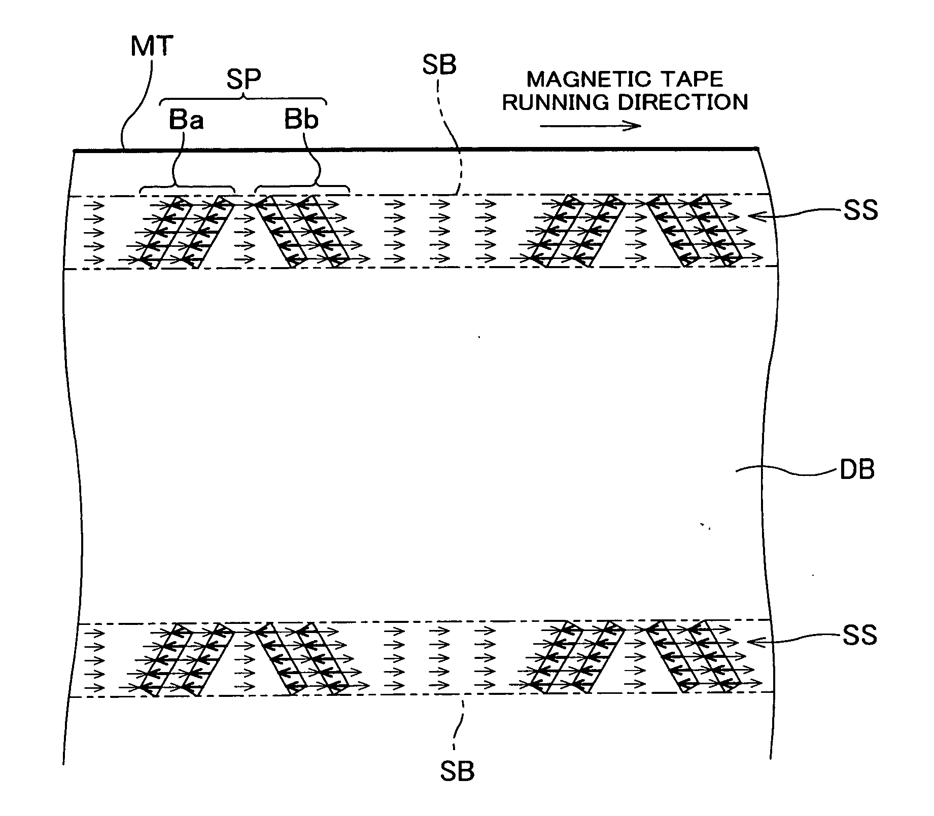
[0110] A description will be given below of a magnetic tape cartridge and a magnetic tape drive according to a second embodiment of the present invention. Contents in this second embodiment differs from those in the first embodiment in that the cartridge memory 2, which is included in the magnetic tape cartridge 1 according to the first embodiment, contains the output level data. The same reference numerals are given to the same parts as those already described in the first embodiment, and duplicate description therefore is omitted. In this embodiment, as with the first embodiment, the servo bands SB1 to SB5 are DC-magnetized in one (forward) direction along the long side of the magnetic tape MT, and the servo signals S1 to S5 are magnetized on the servo bands SB1 to SB5, respectively, in the opposite direction.

[0111] As shown in FIG. 10, the cartridge memory 2 contains the output level data indicating the respective output levels of the servo signals S1 to S5 (only S1 is shown) wr...


PUM


Abstract

Disclosed are a magnetic tape cartridge and a servo writer which both allow a magnetic tape drive to recognize a level of a voltage signal being read from a servo signal. In a magnetic tape included in the magnetic tape cartridge, a servo signal that has been written on a servo band contains output level data indicating an output level of the servo signal itself. The magnetic tape drive reads the servo signal, then extracts the output level data therefrom, and adjusts the output level of the servo signal to a predetermined level.

Description

BACKGROUND OF THE INVENTION [0001] 1. Field of the Invention [0002] Apparatuses and a method consistent with the present invention relate to a magnetic tape cartridge including a magnetic tape within on which servo signals are written, a servo writer for writing servo signals on a magnetic tape, a magnetic tape drive for recording / reproducing data on / from a magnetic tape, and a method for reading servo signals. [0003] 2. Description of the Related Art [0004] In recent years, a high density recording design of magnetic tapes has advanced, and some of magnetic tapes for backup media of computers have a recording capacity of several hundreds of gigabytes. Magnetic tapes therefore have several hundreds of data tracks along the width thereof. Such a high density recording design involves excessive narrowing of the data tracks and of the intervals between the adjacent data tracks in a magnetic tape. Thus, in order to allow recording / reproducing devices of a magnetic head to trace such nar...

Claims


Application Information

Patent Timeline
IPC IPC(8): G11B5/00G11B5/008G11B5/584G11B5/78G11B23/30G11B20/12G11B23/04G11B23/107G11B23/36
CPCG11B5/00813G11B5/584G11B2005/001G11B23/042G11B23/107G11B5/78
Inventor HORIMAI, KIYOSHI
Owner FUJIFILM HLDG CORP
Why Eureka
Try Eureka