Fan stand structure for central processing unit

a technology for central processing and stands, which is applied in the direction of lighting and heating apparatus, electrical apparatus casings/cabinets/drawers, instruments, etc., can solve the problems of damage to the cpu base, unfavorable direct effect of the cpu, and difficulty in fastening the cpu. b, so as to achieve the effect of simple installation and replacement process

Inactive Publication Date: 2005-06-09
TUNG MENG
View PDF7 Cites 7 Cited by
  • Summary
  • Abstract
  • Description
  • Claims
  • Application Information

AI Technical Summary

Benefits of technology

[0008] According to the aforesaid structure, the expanding nail assemblies are inserted through the positioning holes at the four corners of the lower rear panel to become fastened with the upper frame, or the positioning screw assemblies are inserted through the screw holes of the lower rear panel to become fastened with the upper frame. By clamping the motherboard with the upper frame and the lower rear panel, the entire fan stand structure is firmed located at appropriate positions at a periphery of the CPU base, thereby providing simple installation and replacement processes. In addition, points of force application are distributed at the periphery, and therefore vibrations caused by a heat dissipating fan are evenly transmitted to the motherboard to prevent the heat dissipating fan from imposing direct effects on the CPU.

Problems solved by technology

It is to be noted that the heat dissipating fan a2 is fastened at the CPU base c, and vibrations of the heat dissipating fan a2 are likely to cause undesired direct effects on the CPU c1.
When dimensions of the heat dissipating structure a are larger than those of the CPU base c, fastening the heat dissipating structure a using the fastening apparatus b becomes rather difficult, not to mention that breakage of the fastening sections c2 is easily incurred during replacement to further cause damages of the CPU base c.
Nevertheless, such fixed stand d is irreplaceable, and therefore it cannot be replaced once the stand d is damaged.

Method used


Image

  • Fan stand structure for central processing unit
  • Fan stand structure for central processing unit
  • Fan stand structure for central processing unit

Examples


Embodiment Construction

[0015] To better understand the structure, devices and characteristics of the invention, detailed descriptions of a preferred embodiment shall be given with the accompanying drawings below.

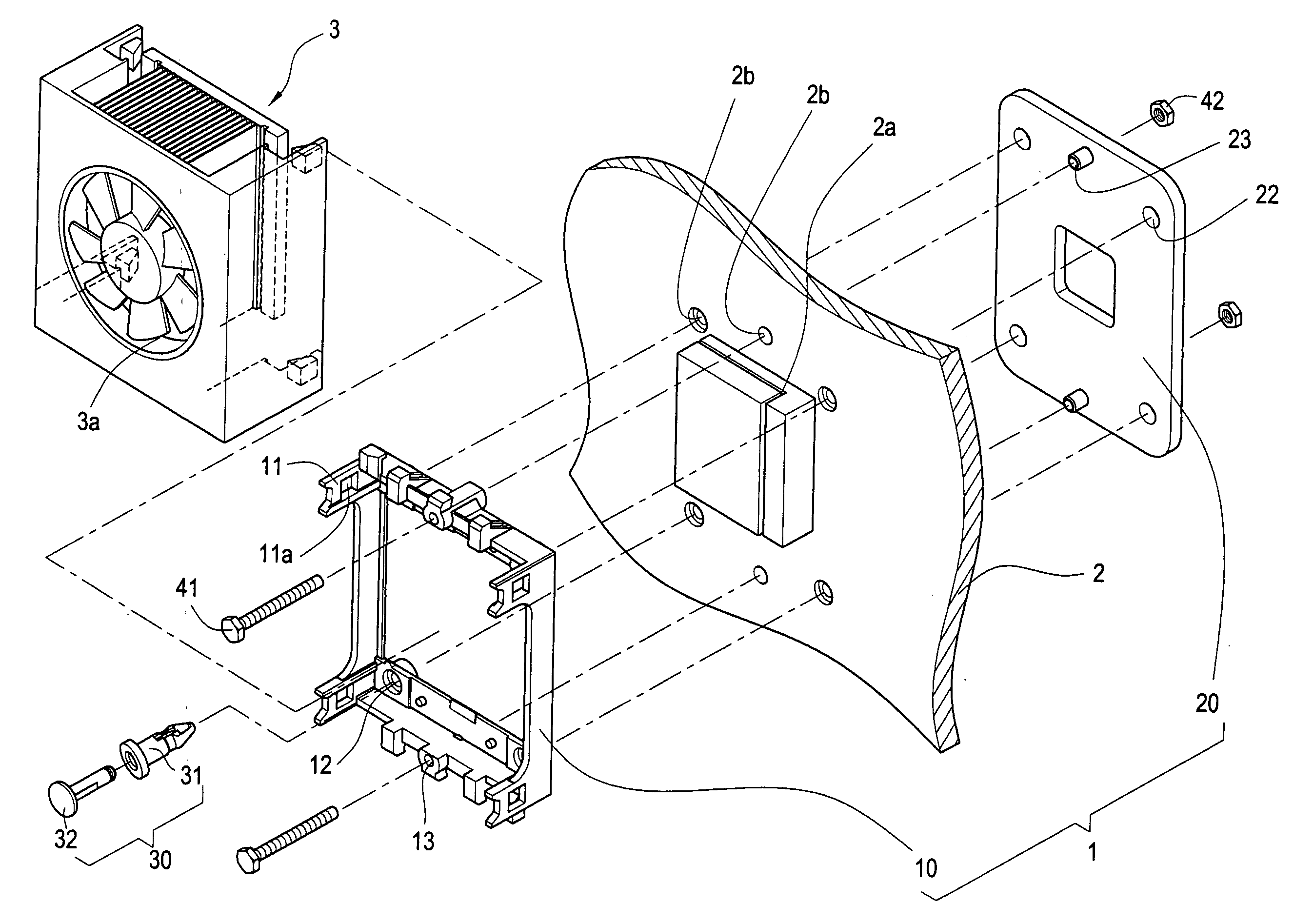
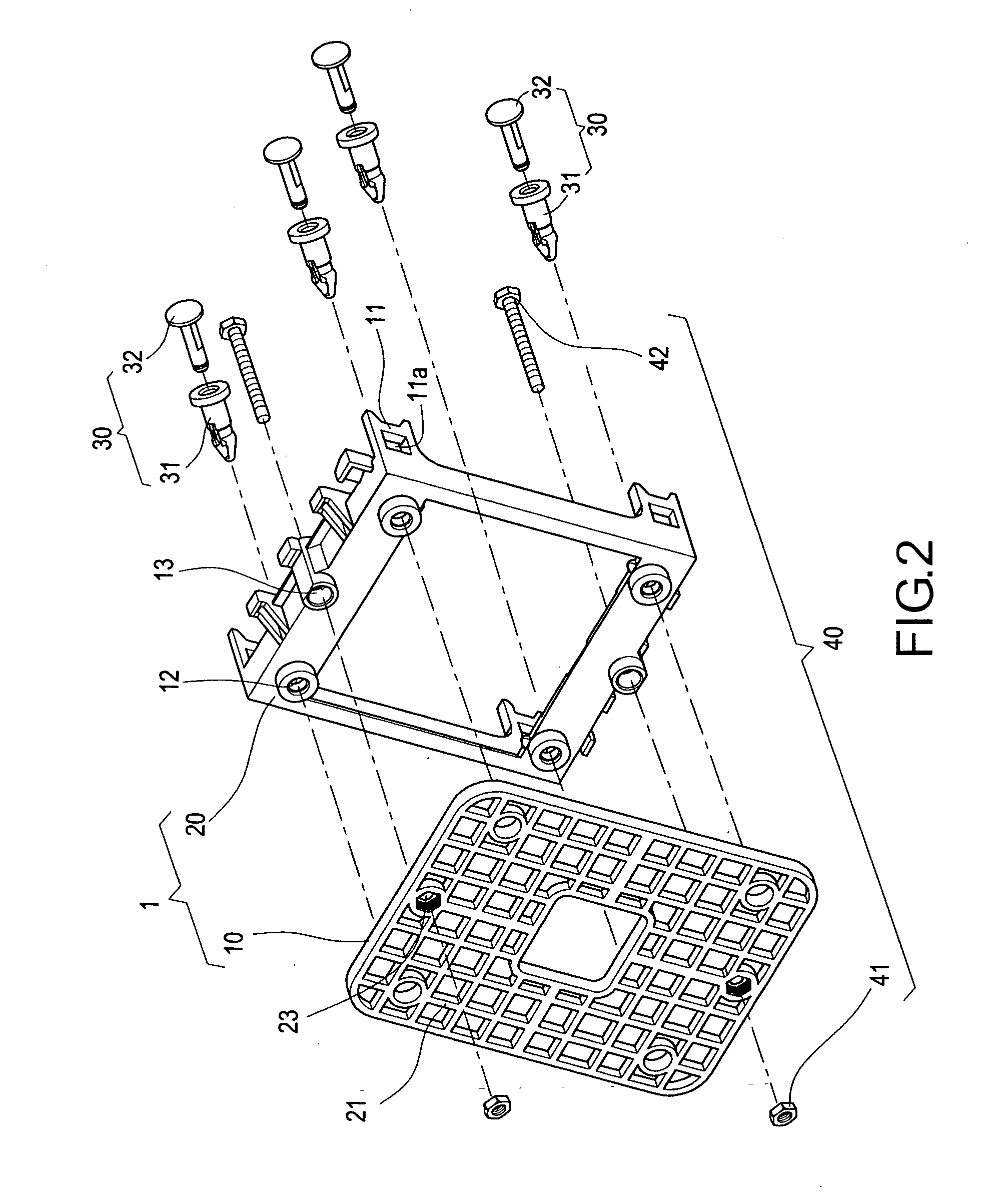
[0016] With reference to FIG. 2 showing a fan stand structure for central processing unit (CPU), a stand structure 1 comprises an upper frame 10, a lower rear panel 20, expanding nail assemblies 30 and positioning screw assemblies 40. The stand structure 1 is an integral formed by plastic extrusion.

[0017] The upper fame 10 appears as a hollow square when viewed from top, and has four supporting arms 11 at two sides thereof. Each supporting arm 11 has a fastening opening 11a at an upper portion thereof. For corresponding with the lower rear panel 20, the upper frame 10 further has positioning holes 12 at four corners thereof, and screw holes 13 at center portions of two sides thereof.

[0018] The lower rear panel 20 is a plate-structure at an obverse side thereof, and has a plurality of reinforcem...


PUM


Abstract

A fan stand structure for central processing unit (CPU), in that the stand structure is for locating a heat dissipating fan of a CPU and provides simple installation and replacement processes as well as good stability, includes an upper frame, a lower rear panel, expanding nail assemblies and positioning screw assemblies. The invention is characterized, the lower rear panel is placed at a reverse side and the upper frame is installed at an obverse side of the CPU base of the motherboard, respectively. Using the expanding nail assemblies and the positioning screw assemblies for locating the upper frame and the lower rear panel, a heat dissipating fan is installed at supporting arms of the upper frame, thereby providing a fan stand with simple installation and replacement processes as well as good stability.

Description

BACKGROUND OF THE INVENTION [0001] (a) Field of the Invention [0002] The invention relates to a fan stand structure for central processing unit (CPU), and more particularly, to a stand structure for fixing a heat dissipating fan of a CPU, in that the stand structure comprises a lower rear panel and an upper frame. [0003] (b) Description of the Prior Art [0004] With reference to FIG. 1A, a prior central processing unit (CPU) heat dissipating structure a is generally mounted on a CPU base c using a fastening apparatus b, and is located closely to cooling fins a1 and a CPU c1. Heat produced by the CPU c1 is transmitted to the cooling fins a1, and is overblown by the heat dissipating fan a2 situated above. The fastening apparatus c is mostly devised with fastening openings b1 at two ends thereof for fixing with fastening sections c2 at two sides of the CPU base c. This prior structure indeed offers practical conveniences and satisfactory stability. However, thermal energy is relatively ...

Claims


Application Information

Patent Timeline
Patent Type & Authority Applications(United States)
IPC IPC(8): H01L23/40H01L23/467H05K7/20
CPCH01L23/4006H01L23/467H01L2924/0002H01L2924/00
Inventor TUNG, MENG
Owner TUNG MENG
Why Eureka
Try Eureka