Method of and control node for detecting failure

Inactive Publication Date: 2005-06-09
FUJITSU LTD
View PDF6 Cites 26 Cited by
  • Summary
  • Abstract
  • Description
  • Claims
  • Application Information

AI Technical Summary

Benefits of technology

[0027] The method as described above eliminates a need to exchange a message both ways be

Problems solved by technology

Because of this limitation, this method cannot be applied to a network in which all the paths are cross-connected through optical signals.
This method of recovering from failure cannot be applied if relay nodes that do not perform optical-to-electrical conversion are requir

Method used


Image

  • Method of and control node for detecting failure
  • Method of and control node for detecting failure
  • Method of and control node for detecting failure

Examples


first embodiment

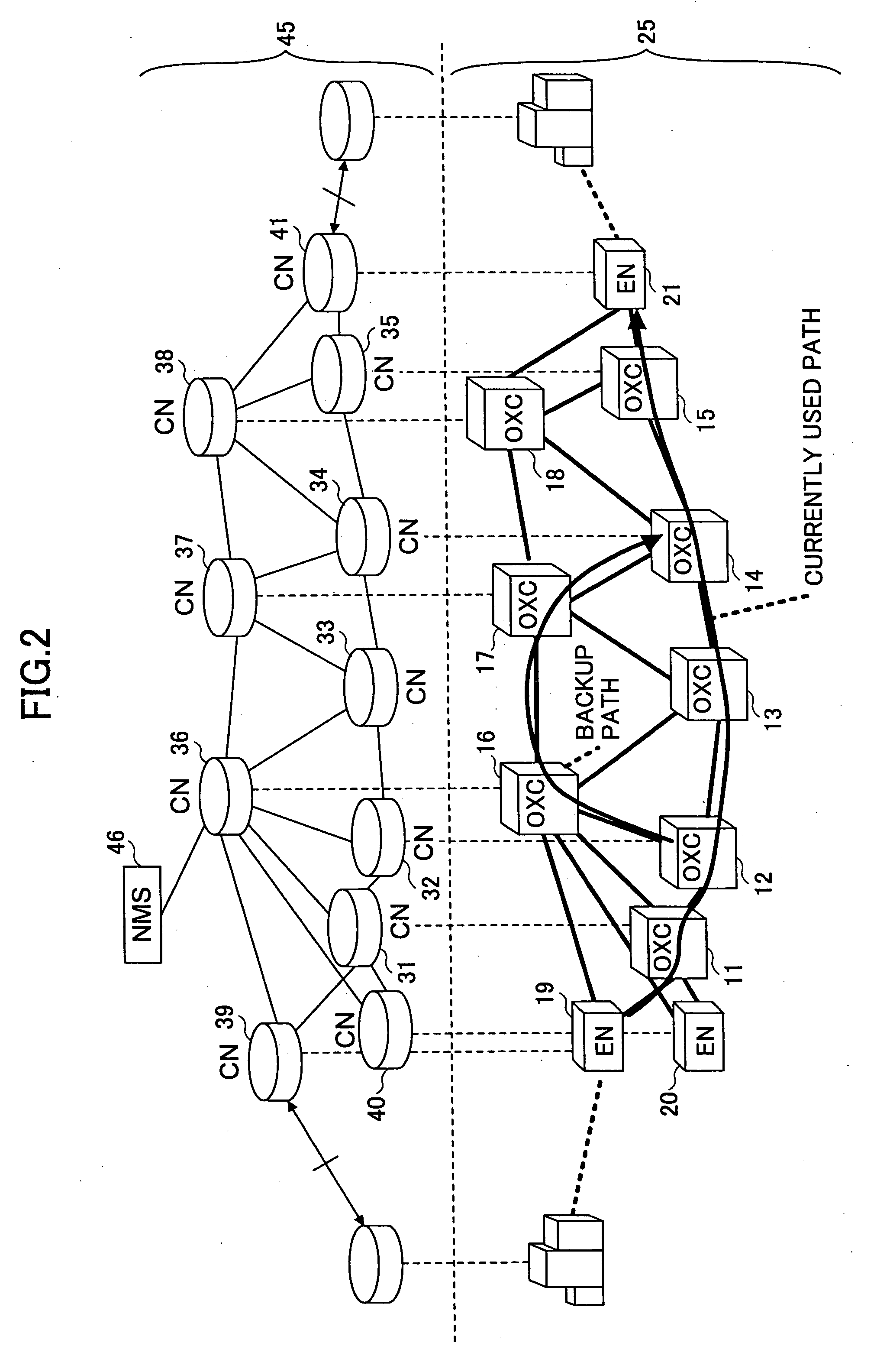
[0073]FIG. 6 is an illustrative drawing showing the construction of a network for explaining a method of detecting a link failure according to the invention. In FIG. 6, the same elements as those of FIG. 2 are referred to by the same numerals. In FIG. 6, when an optical signal is disconnected due to link severance between the optical cross-connects 12 and 13, all the optical cross-connects 13, 14, and 15 provided downstream relative to the point of link severance detect an optical disconnection failure. Here, the term “downstream” refers to a direction from a start node of a path to an end node that terminates the path. The term “upstream” is used to refer to an opposite direction.

[0074] For the purpose of bypassing the failure, a backup path provided along the optical cross-connects 12, 16, 17, and 14 can be used. The point of a failure, however, needs to be identified first. To this end, failure information transmitted by the control nodes 33, 34, and 35 is given respective time s...

second embodiment

[0082]FIG. 10 is an illustrative drawing showing the construction of a network for explaining a method of detecting a link failure according to the invention. In FIG. 10, the same elements as those of FIG. 2 are referred to by the same numerals. In FIG. 10, the control node 33 having detected a failure transmits a failure information message having the format as shown in FIG. 7A for the purpose of notifying of the occurrence of a failure. This transmission is directed to the control node 34 provided downstream on the path on which the failure is detected. Having received the failure information message, the control node 34 recognizes that a failure has occurred upstream on the above-noted path.

[0083] The control node of interest can ascertain that its own node position is the point of link failure if the failure information message is transmitted downstream and if no failure information message is received from upstream on the path.

[0084] Furthermore, a timer is provided that start...

third embodiment

[0089]FIG. 12 is an illustrative drawing showing the construction of a network for explaining a method of detecting a link failure according to the invention. In FIG. 12, the same elements as those of FIG. 2 are referred to by the same numerals. In FIG. 12, each of the control nodes 33, 34, 35, and 41 having detected a failure transmits a failure information message for the purpose of notifying of failure occurrence to the control nodes 32, 33, 34, and 35 provided upstream. Having detected the failure information message, each of the control nodes 32, 33, 34, and 35 transmits a response message to the downstream control nodes 33, 34, 35, and 41. Here, the response message indicates whether a failure is detected at its own control node.

[0090]FIGS. 13A and 13B are drawings showing the format of a failure information message and the format of a response message according to the second embodiment. As shown in FIG. 13A, the failure information message includes a common header and a messa...


PUM


Abstract

A method of detecting a failure in a network, which includes a transport plane comprised of a plurality of communication nodes performing optical cross-connect and a control plane comprised of a plurality of control nodes that are connected to and control the respective communication nodes, includes the steps of transmitting, from a control node connected to a communication node having detected a failure to an adjacent control node, a failure information message having a time indication indicative of a time at which the failure is detected, and identifying, at a given control node which received the failure information message, a location of the failure in response to the time indication.

Description

BACKGROUND OF THE INVENTION [0001] 1. Field of the Invention [0002] The present invention generally relates to a method of and apparatus for detecting a network failure, and particularly relates to a method of and an apparatus for detecting a failure of an optical network. [0003] 2. Description of the Related Art [0004] Network traffic has been increasing at a rapid rate, and, also, there has been the emergence of services such as VoIP (Voice over Internet Protocol) that require real-time properties. Against this background, there is an urgent need for the provision of a transport network that achieves high capacity and flexible network control. [0005] In order to provide such network, it is necessary to incorporate IP technology capable of flexible network control into a transport network. Organizations for standardization have been studying relevant network architectures and the detail of protocols. [0006] The formulation of specifications for the GMPLS (generalized MPLS) signalin...

Claims


Application Information

Patent Timeline
IPC IPC(8): H04J14/02H04M3/22H04L69/40H04Q11/00
CPCH04J14/0227H04J14/0284H04L41/0677H04J14/0241H04Q2011/0081H04Q2011/0088H04Q11/0062
Inventor SOUMIYA, TOSHIOKANO, SHINYA
Owner FUJITSU LTD
Why Eureka
Try Eureka