Thermal analyzer with gas mixing chamber

Active Publication Date: 2005-06-09
HITACHI HIGH TECH SCI CORP
View PDF5 Cites 33 Cited by
  • Summary
  • Abstract
  • Description
  • Claims
  • Application Information

AI Technical Summary

Benefits of technology

[0009] In the thermal analyzer constituted as described above, since the sample chamber, the detector chamber, and the gas mixing chamber are separated from one other by the partition walls, gasses passing through the sample chamber and the detector chamber are fed independently from the sample chamber and the detector chamber, respectively. Thus, the gasses are never mixed. In

Problems solved by technology

Therefore, the bar probe cannot measure a change in a physical amount of a sample ac

Method used


Image

  • Thermal analyzer with gas mixing chamber
  • Thermal analyzer with gas mixing chamber
  • Thermal analyzer with gas mixing chamber

Examples


Embodiment Construction

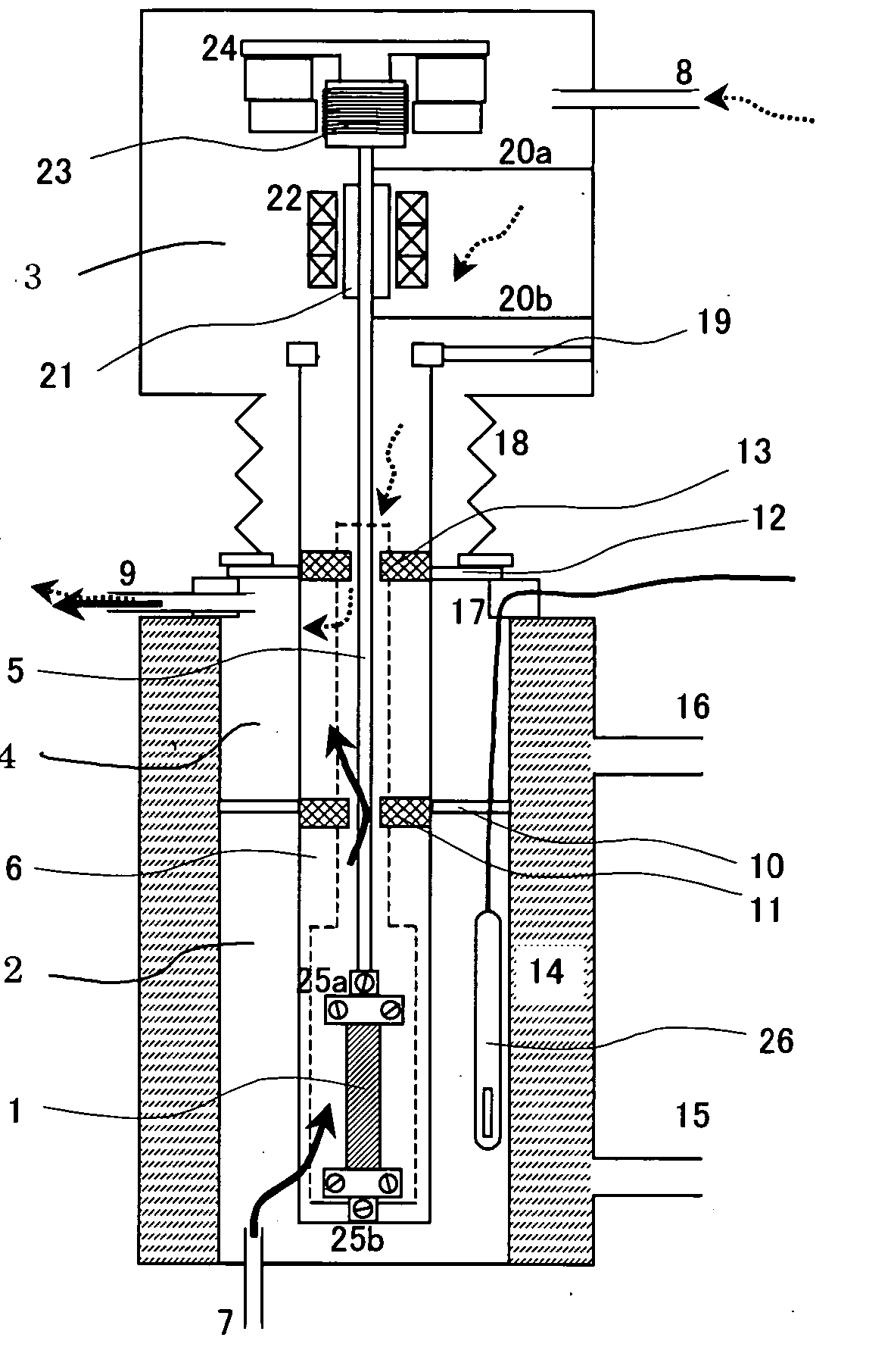
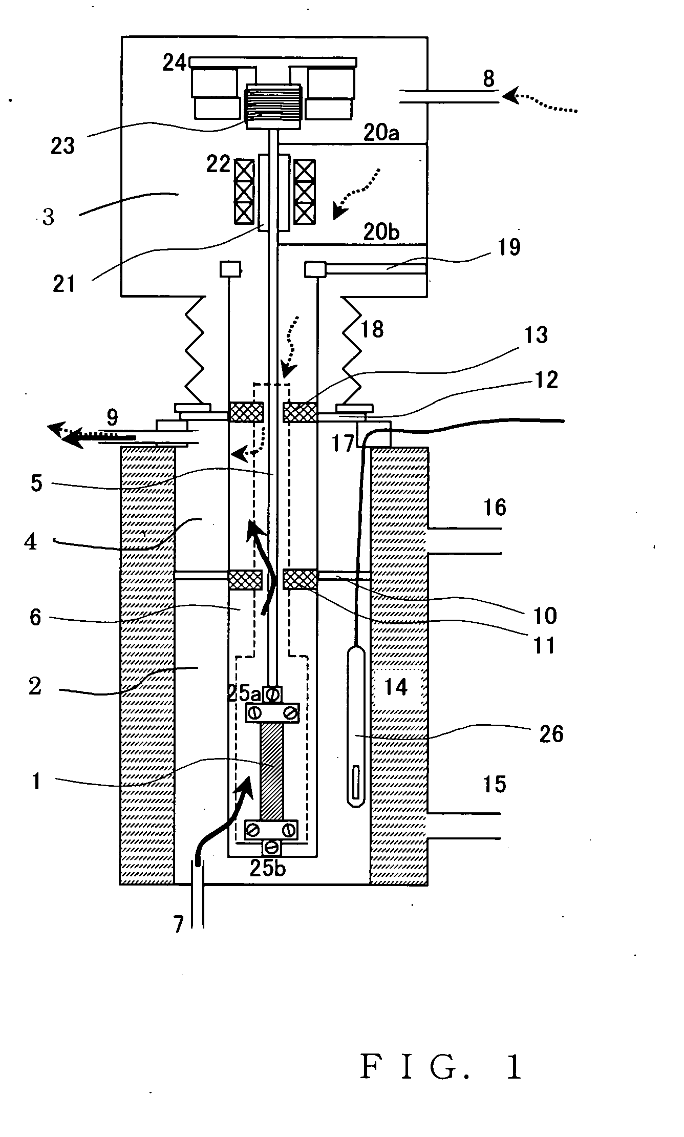
[0016] An embodiment of the invention will be explained with reference to the accompanying drawings. FIG. 1 is a longitudinal sectional view of a thermal analyzer according to the invention. A type of the thermal analyzer is a thermomechanical measuring device (TMA). This is an example of a device that is capable of performing measurement as a humidity control type TMA assuming the air having an adjusted water vapor partial pressure as an atmospheric gas around a sample.

[0017] In FIG. 1, in an entire structure of the thermal analyzer, a sample chamber 2 is provided in a lower part, a detector chamber 3 is provided in an upper part, and a gas mixing chamber 4 is provided in the center to be placed between the sample chamber 2 and the detector chamber 3. A gas containing a water vapor gas indicated by a solid line arrow is fed to the sample chamber 2. On the other hand, a dry gas indicated by a dotted line arrow is fed to the detector chamber 3. The two kinds of gasses are mixed in t...


PUM


Abstract

In a thermomechanical measuring device and a thermogravimetry device, partition walls are provided in two sections such that two kinds of atmospheric gasses, which have passed a sample chamber and a detector chamber, respectively, do not flow back, and a thermally insulated gas mixing chamber is manufactured anew in the middle of the sample chamber and the detector chamber to make it possible to dilute a reactive gas and a water vapor gas having a high partial pressure. Consequently, it is possible to prevent moisture concentration to reduce an influence of water drops even in a high temperature and high humidity state at the time of humidity control and measurement.

Description

BACKGROUND OF THE INVENTION [0001] The present invention relates to a thermal analyzer including a sample chamber and a detector chamber that houses a detector for detecting a physical change due to temperature of a sample stored in the sample chamber as a displacement. [0002] In the thermal analyzer including the sample chamber and the detector chamber that houses the detector for detecting a physical change due to temperature of a sample stored in the sample chamber as a displacement, when a gas is fed, different kinds of gasses are used as an atmospheric gas in the sample chamber and am atmospheric gas in the detector chamber that is provided to be connected to the sample chamber via a tubular member. In particular, when an atmospheric gas around a sample contains water vapor, a purge gas for protecting this water moisture from condensing on the detector is introduced into the detector. [0003] In such a case, in the conventional thermal analyzer, an exhaust port is provided in th...

Claims


Application Information

Patent Timeline
IPC IPC(8): G01N25/18G01N3/02G01N5/04G01N25/16
CPCG01N5/04G01N25/16G01N2203/0282G01N2203/024G01N2203/0222
Inventor NAKAMURA, TOSHIHIKO
Owner HITACHI HIGH TECH SCI CORP
Why Eureka
Try Eureka