Burnishing burr drill

a burr drill and burr technology, applied in metal-working equipment, metal-working equipment, milling equipment, etc., can solve the problems of affecting the feed speed, the cutting edge pair, and the time and power consumption, and achieve the effect of high feed speed and higher strength

Inactive Publication Date: 2005-06-09
ZHOU QING
View PDF6 Cites 15 Cited by
  • Summary
  • Abstract
  • Description
  • Claims
  • Application Information

AI Technical Summary

Benefits of technology

[0007] Therefore, the main object of the invention is to provide a burnishing Burr drill with more than two cutting edges which is able to obtain a high feed speed at the same time. Another o

Problems solved by technology

Whenever a fine wall of a hole drilled by large teeth is needed, a fine teeth drill must be used to further work on the hole, which takes time and power.
However, this drill has three drawbacks.
First, the drill only has a pair of cutting edges.
This heavily negatively affected a feed speed thereof.
In fact, when quantity of cutting edges is reduced as many as two, a high feed

Method used


Image

  • Burnishing burr drill
  • Burnishing burr drill

Examples


Embodiment Construction

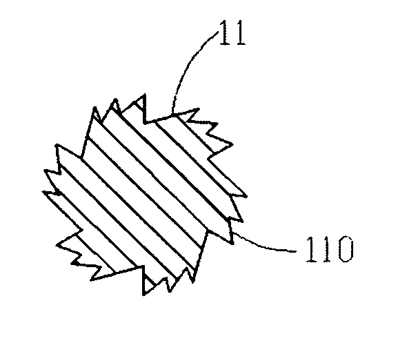
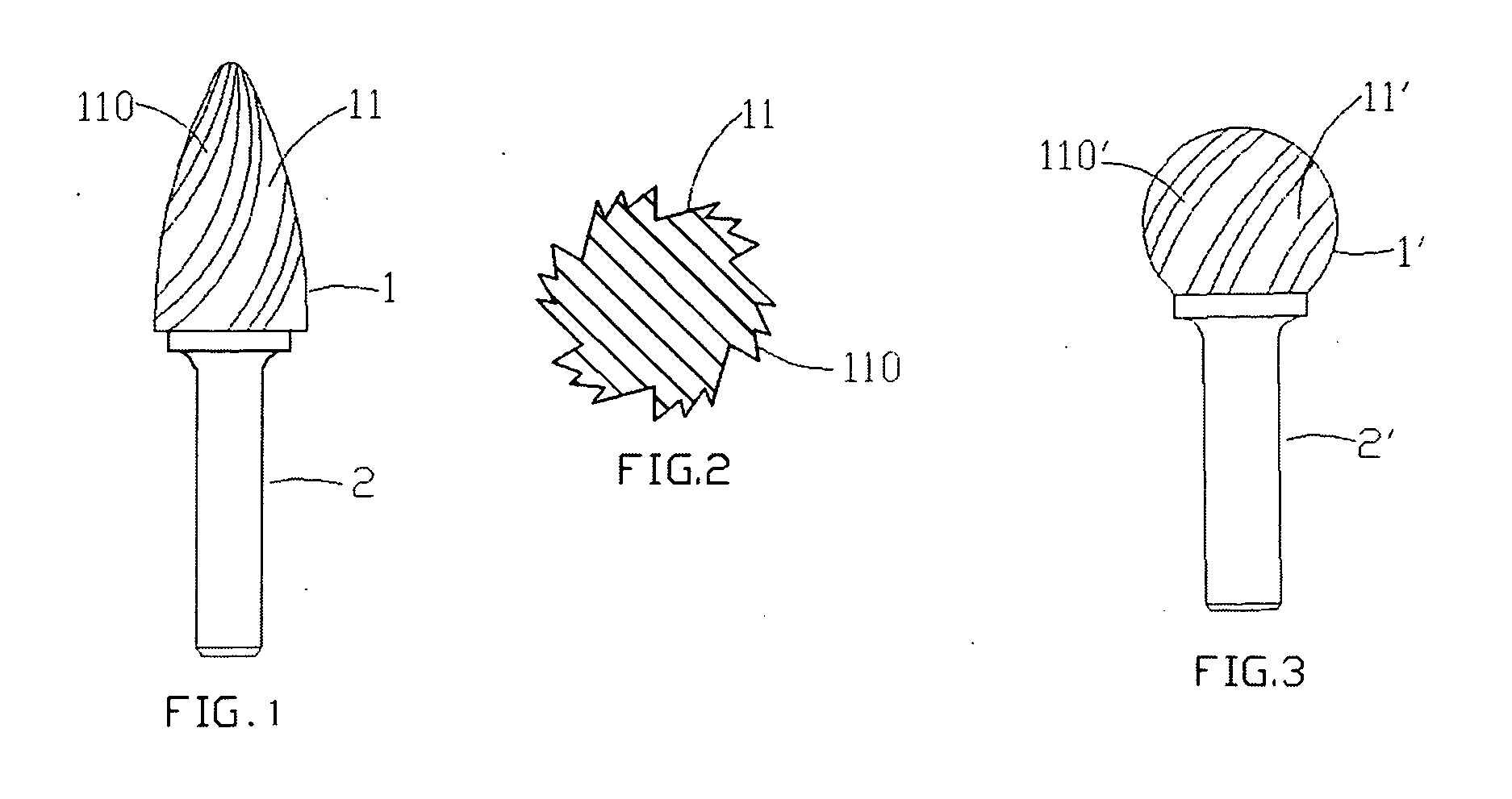
[0012] With reference to FIGS. 1 and 2, a burnishing Burr drill of the invention is shown. The burnishing Burr drill has a drill head 1 and a shank 2 connected thereto and longitudinally extends downward. The drill head 1 shown in the Figs. is bullet-head shaped. The drill head 1 has more than two, preferably more than 5, large teeth 11 mainly used for cutting and obtaining most feed speed. Each large teeth 111 has a front surface 12 and a back surface 13. More than one small tooth 131 is formed on the back surface 13 of each large tooth 11. In use, when the drill head 1 works on a workpeice, the large teeth 11 cut the workpeice material first will define a hole in the workpeice. As the burnishing drill feed forward, the small teeth 131 meet a surface of the hole and further finish a wall of the hole.

[0013] As shown in FIG. 3, the drill head 1 can be made ball-shaped.

[0014] Although the present invention has been described in detail, it should be understood that various changes, c...


PUM


Abstract

A burnishing Burr drill having more than two large teeth and more than one small tooth formed on each back surface of the large tooth is disclosed. Large teeth is mainly used for cutting and obtaining a high feed speed. As the burnishing drill feed forward, the small teeth will meet a surface of a hole drilled by the large teeth and further finish a wall of the hole.

Description

RELATED APPLICATIONS [0001] This application is a continuation-in-part application of the U.S. patent application Ser. No. 10 / 384,891, filed on Mar. 10, 2003, now abandoned, the contents of which are herein incorporated by reference.BACKGROUND OF THE PRESENT INVENTION [0002] 1. Field of the Present Invention [0003] The invention relates to a burnishing Burr drill, and more particularly, to a Burr drill having a plurality of large teeth each having more than one fine teeth on a back thereof. The burnishing Burr drill of the invention therefore is able to drill a hole with a polished wall while keeping a relatively high feed speed. [0004] 2. Description of Related Arts SUMMARY OF THE PRESENT INVENTION [0005] Conventional drills usually have a shank and a head integrally formed thereon. The heads have more than one teeth used for cutting. Sizes of the teeth differ from one to another according to various uses thereof. For example, generally large teeth are used to obtain a high feed sp...

Claims


Application Information

Patent Timeline
IPC IPC(8): B23C5/10
CPCB23C5/10B23C5/1009Y10T407/1946B23C2220/605B23C2265/08B23C2210/326
Inventor ZHOU, QING
Owner ZHOU QING
Why Eureka
Try Eureka