Combine chaff discharger

a chaff discharger and chaff technology, applied in the field of chaff dischargers, can solve the problems of difficult or even impossible to locate the chaff discharger, difficult satisfactorily, and large amount of smoke and dust around

Inactive Publication Date: 2005-06-09
REKORDVERKEN SWEDEN
View PDF20 Cites 33 Cited by
  • Summary
  • Abstract
  • Description
  • Claims
  • Application Information

AI Technical Summary

Benefits of technology

[0015] Yet another object of the invention is to make it possible to achieve this freedom of choice by technically and functionally simple and efficient means.

Problems solved by technology

During the threshing operation considerable amounts of smoke and dust are generated around the combine, which is a serious problem as regards the combine drive motor and above all considering the substantial fire hazard involved.
In some types of combine harvesters, various circumstances, such as lack of space or different structural or functional / technical solutions, make it very difficult or even impossible to so locate the chaff discharger that without problems the chaff may be mixed with or blown into the straw, to be chopped in the straw chopper, upstream of the latter.
Furthermore, in some cases, particularly when large volumes of chaff (and husks) are to be handled, it may be difficult satisfactorily and without unnecessary waste to blow the chaff through the open through-passage in the deflector plate to the straw chopper.
In addition, because the chaff is mixed into the straw to be chopped upstream of the straw chopper it may in some cases happen, for example when the volumes of straw and chaff are large or when the moisture contents of that material are high, that the straw chopper becomes overloaded or clogged.
In turn, this may lead to impaired spreading of the chopped straw jointly with the at least partly chopped chaff and, if the worst comes to the worst, even to breakdown.
On the other hand, when the control is effected by electrical or hydraulic means or in some other way by means of controls installed in the driver's cabin, the operator need not leave the driver's cabin but on the other hand, rather expensive and complex installation of the controls in the cabin is required as also mounting of the drive means in the form of motors, valves and so on on the chaff discharger in order to rotate the associated fan housing, as well as operational lines / hoses / tubes extending between the driver's cabin and the chaff discharger.

Method used


Image

  • Combine chaff discharger
  • Combine chaff discharger
  • Combine chaff discharger

Examples


Embodiment Construction

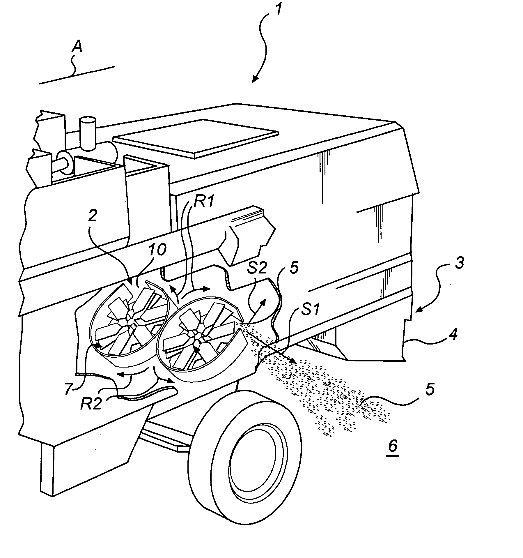
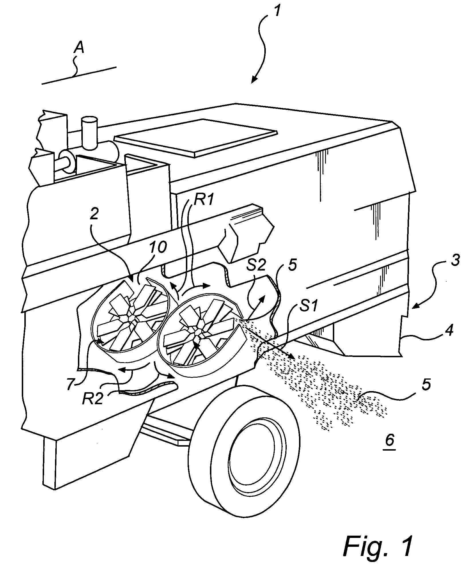
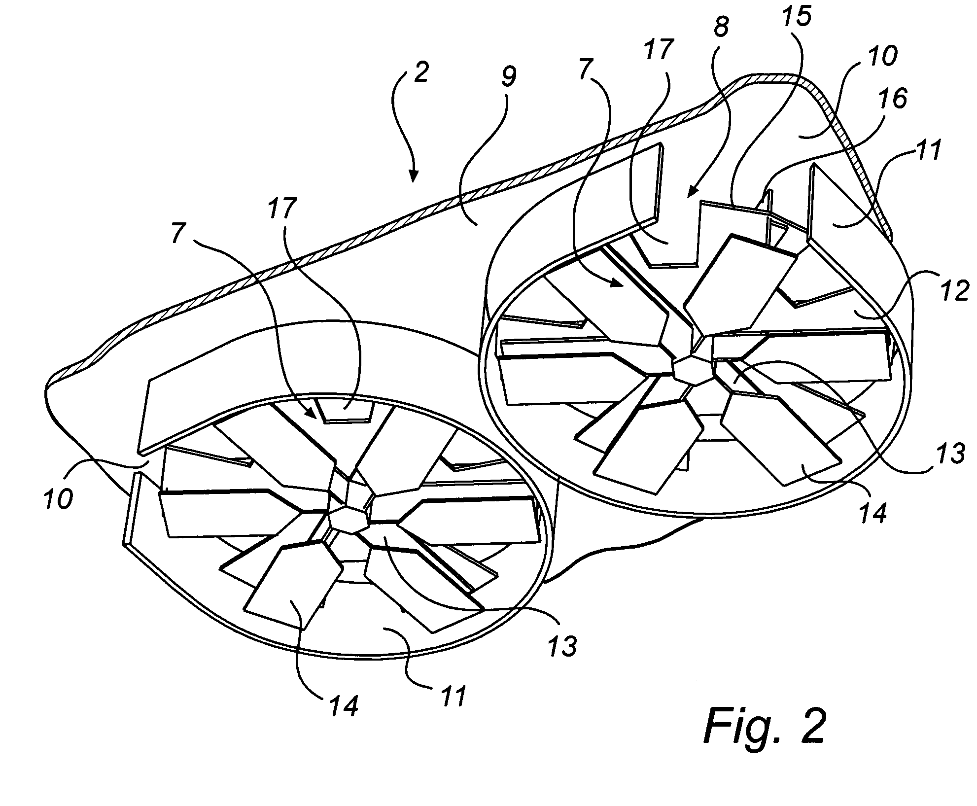
[0029] With the exception of the chaff discharger in accordance with the invention, generally designated by reference 2, the combine harvester generally designated in the drawings by reference 1 is of conventional design comprising a pick-up reel, not shown, and a cutting table, not shown either, which has a width considerably exceeding that of the combine harvester 1. The crop material, in this case straw fodder plants or the like that are to be harvested, is cut on the cutting table and is forwarded via conveyors or the like, not shown, to a thresher, not shown either, in which straw and grains are separated from one another, not shown.

[0030] The straw is forwarded via a conventional straw shaker, not shown, or alternatively a threshing cylinder or the like, to a straw chopper 3, which is located at the rear end of the combine harvester 1 as seen in the direction of travel A of the combine. Thus, the straw chopper is located downstream of the straw shaker and on the whole it is c...


PUM


Abstract

A chaff discharger (2) intended for a combine harvester (1) for discharge of chaff (5) from a sieving on the combine, is positioned downstream of the sieving unit and has least one radial fan wheel (7), which is rotationally mounted in a fan housing (8), said housing having an end wall (9), which is turned away from the sieving unit, and an peripheral wall (11), in which is formed at least one chaff discharge opening (10). The direction of rotation (R1, R2) of the fan wheel is reversible so as to permit discharge of the chaff (5) in different directions (S1, S2) via the associated chaff discharge opening (10), depending on the fan wheel direction of rotation.

Description

TECHNICAL FIELD OF INVENTION [0001] The present invention relates to a chaff discharger, which is intended for use in a combine harvester for discharge of chaff from a sieving unit on the combine, said chaff discharger being positioned downstream of the sieving unit and having at least one radial fan wheel, which is rotatably mounted in a fan housing, said housing having an end wall, which is turned away from the sieving unit and a peripheral wall, formed with at least one chaff discharge opening. BACKGROUND OF THE INVENTION [0002] In threshing operations carried out in combine harvesters, harvest residues are produced, normally consisting of chaff and straw from such crops as wheat, barley, oats and rye but also originating from different kinds of oil-producing plants and maize, sunflower and so on having comparatively large and stiff plant parts. For the sake of simplicity and clarity, the terms chaff and straw will, however, be used throughout. [0003] Modern combine harvesters ar...

Claims


Application Information

Patent Timeline
Patent Type & Authority Applications(United States)
IPC IPC(8): A01D41/12
CPCA01D41/1243
Inventor HOLMEN, BENGT
Owner REKORDVERKEN SWEDEN
Why Eureka
Try Eureka