Anatomical interbody implant and gripper for same

Inactive Publication Date: 2005-06-09
BERNARD PIERRE M +1
View PDF8 Cites 92 Cited by
  • Summary
  • Abstract
  • Description
  • Claims
  • Application Information

AI Technical Summary

Benefits of technology

[0012] Another object of the invention is thus to provide an instrument for manipulating a cage in the general sense, regardless of whe

Problems solved by technology

Unfortunately, while the instrument is manipulating the cage, there is a risk of the cage becoming separated

Method used


Image

  • Anatomical interbody implant and gripper for same
  • Anatomical interbody implant and gripper for same
  • Anatomical interbody implant and gripper for same

Examples


Embodiment Construction

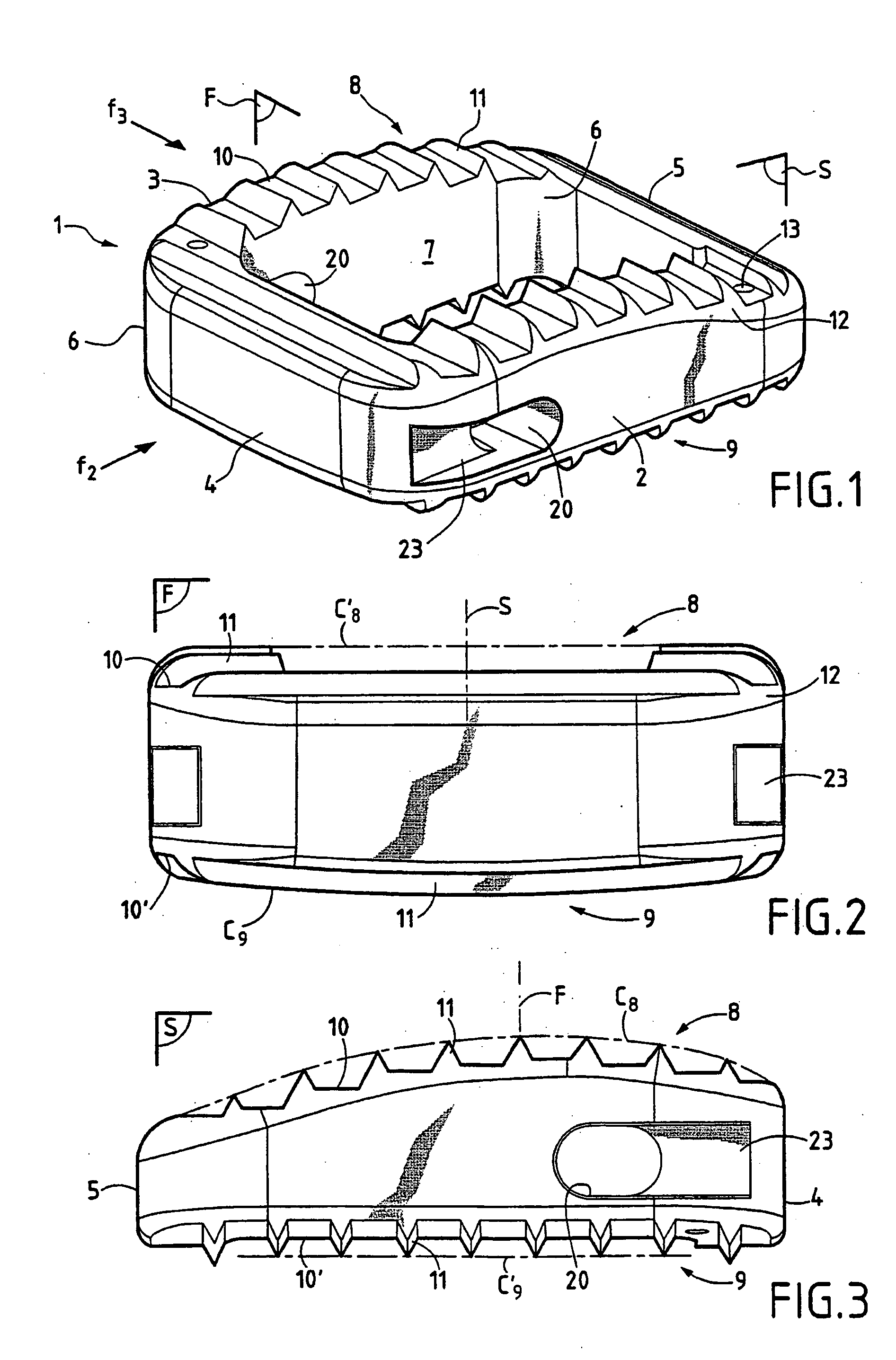
[0022] As can be seen more precisely in FIGS. 1 to 3, an intersomatic implant in accordance with the invention is in the form of a cage 1 which is generally in the form of a rectangular block and is designed to be inserted in the disk space between two adjacent vertebrae, e.g. cervical vertebrae. The cage 1 has a first sagittal wall 2 and a second sagittal wall 3 extending substantially parallel to each other and to a “sagittal” or “antero-posterior” plane S. The sagittal walls 2 and 3 are interconnected by an “anterior” transverse wall 4 and by a “posterior” transverse wall 5 extending parallel to each other and to a frontal plane F extending perpendicularly to the sagittal plane S.

[0023] It should be observed that the cage 1 can have one or more intermediate or mid walls extending substantially parallel to the sagittal and / or transverse walls. Preferably, connecting fillets 6 are provided between the sagittal walls and the transverse walls firstly along their internal vertical fa...


PUM


Abstract

The invention relates to an intersomatic implant designed to be inserted in the disk space defined between two adjacent vertebrae, namely an overlying vertebra and an underlying vertebra, for the purpose of reestablishing the anatomic space between the vertebrae, the implant being in the form of a cage (1) that is generally in the shape of a rectangular block having at least two sagittal walls (2, 3) interconnected at least by an anterior transverse wall (4) and by a posterior transverse wall (5), the walls (2 to 5) presenting rims (10) extending on one surface to define a first transverse face (8) and on the other side to define a second transverse face (9). According to the invention, the implant comprises:
    • a first transverse face (8) presenting in the sagittal plane a convex profile congruent with the sagittal anatomic profile of an overlying vertebra; and a second transverse face presenting in the frontal plane a convex profile congruent with the frontal anatomic profile of an overlying vertebra.

Description

TECHNICAL FIELD [0002] The present invention relates to an intersomatic implant for insertion into the disk space defined between two adjacent vertebrae, in order to restore an appropriate height between the vertebrae and in order to allow bone fusion to take place between said adjacent vertebrae. [0003] More precisely, the invention provides an intersomatic implant of the cervical type, for insertion into the disk space defined between two adjacent cervical vertebrae. PRIOR ART [0004] In the state of the art, it is known to insert an intersomatic implant into the disk space between defined between two adjacent cervical vertebrae. Numerous embodiments of such intersomatic implants are proposed in the prior art. For example, a known cervical intersomatic implant is in the form of a cage comprising two sagittal walls interconnected by a anterior transverse wall and by a posterior transverse wall. Between them, the walls define an open volume for receiving a bone-filler substance for e...

Claims


Application Information

Patent Timeline
IPC IPC(8): A61F2/00A61F2/28A61F2/30A61F2/44A61F2/46
CPCA61F2/442A61F2250/0098A61F2/4611A61F2002/2835A61F2002/3008A61F2002/30266A61F2002/30271A61F2002/30324A61F2002/30777A61F2002/30828A61F2002/30848A61F2002/30879A61F2002/30892A61F2002/4475A61F2002/4622A61F2002/4628A61F2230/0082A61F2250/0036A61F2/447A61F2002/30261A61F2002/30593A61F2002/30845
Inventor BERNARD, PIERRE M.POINTILLART, VINCENT
Owner BERNARD PIERRE M
Why Eureka
Try Eureka