Biliary stent introducer system

Inactive Publication Date: 2005-06-09
WILSONCOOK MEDICAL
View PDF98 Cites 74 Cited by
  • Summary
  • Abstract
  • Description
  • Claims
  • Application Information

AI Technical Summary

Benefits of technology

[0004] In one aspect of the invention, the stent delivery system includes a first introducer, a second introducer and an endoscope having a working channel. The first and second introducers are adapted to be disposed in an adjacent configuration within the working channel of the endoscope. The first introducer comprises a first outer catheter and a first inner shaft having a first stent retaining area located on a distal portion of the first inner shaf

Problems solved by technology

However, currently available stent and introducer geometries are such that placement of a first stent may interfere with the placement of a second stent. FIG. 3 illustrates the problem associated with the prior art method of placing stents in

Method used


Image

  • Biliary stent introducer system
  • Biliary stent introducer system
  • Biliary stent introducer system

Examples


Embodiment Construction

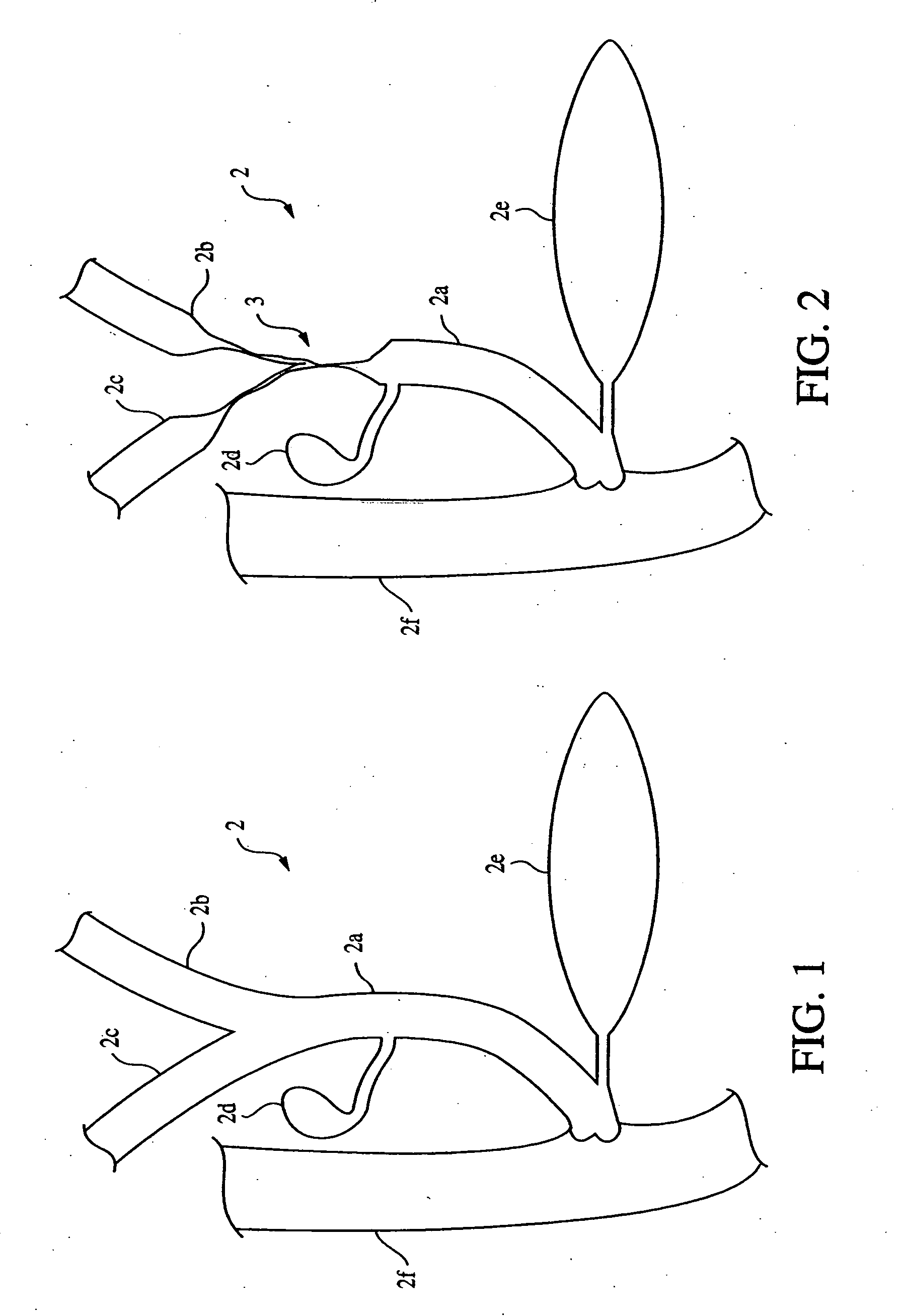
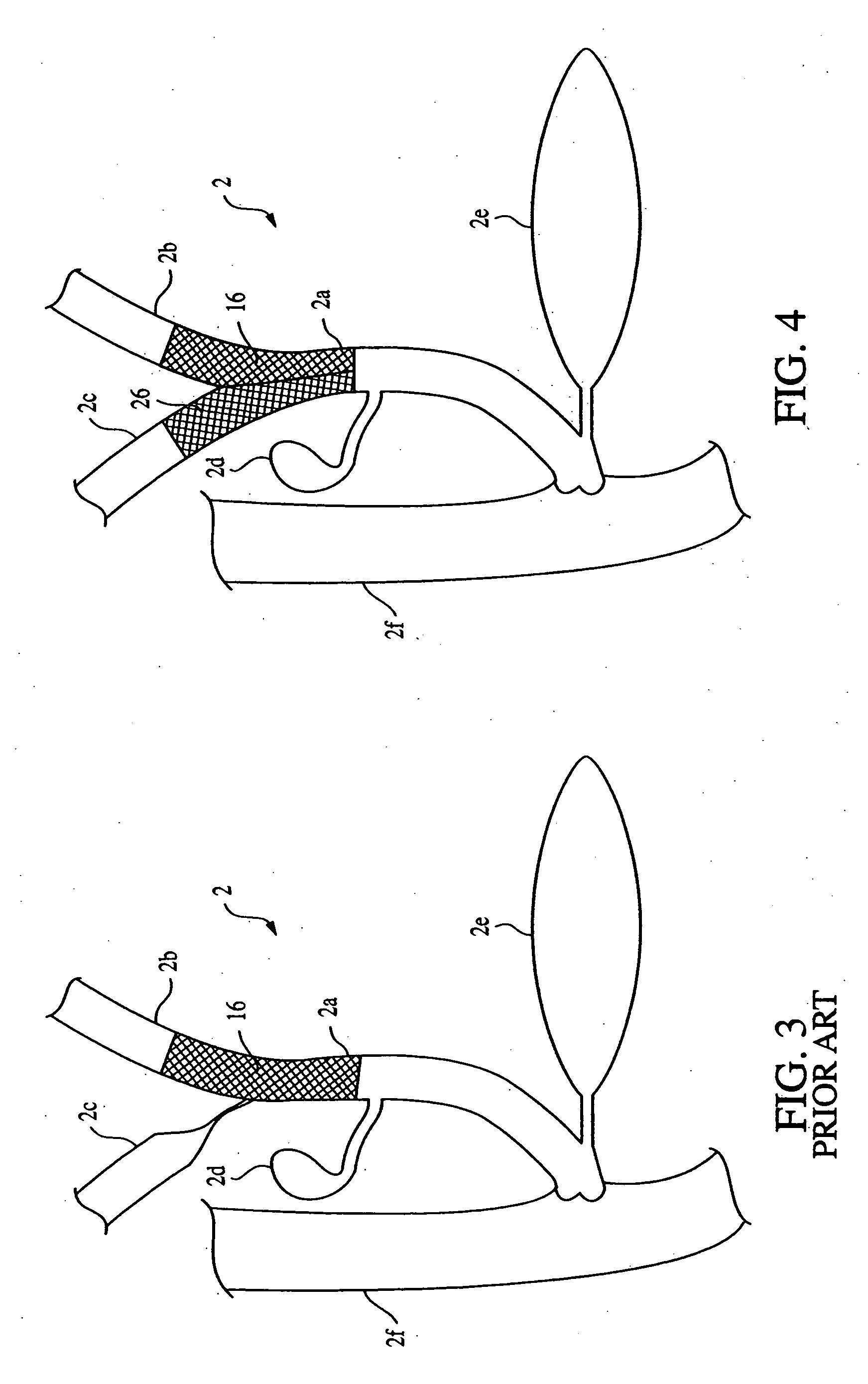
[0029] Referring now to the Figures wherein like numerals indicate the same element throughout the views, there is shown in FIGS. 1-2 and 4 a bifurcation comprising a main lumen, a first branch lumen and a second branch lumen. In particular, these figures illustrate a bifurcation in the biliary system, wherein the main lumen comprises the common bile duct 2a and the first and second branch lumens comprise the left and right hepatic ducts 2b, 2c respectively. FIG. 1 shows a normal, or healthy, biliary system with no strictures. FIG. 2 shows the biliary system with strictures 3 residing in the main lumen and in both branch lumens of the bifurcation. FIG. 4 shows a pair of stents placed in the left and right hepatic ducts 2b, 2c, respectively, and the common bile duct 2a according to a preferred method of the present invention.

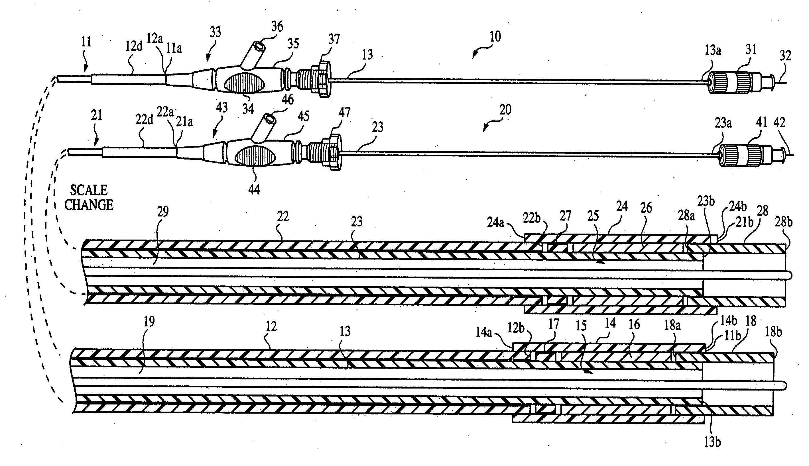
[0030] Referring now to FIGS. 12 and 13, a stent delivery system 1 made in accordance with the present invention is shown. Stent delivery system 1 comprises a f...


PUM


Abstract

A stent delivery system and method for positioning a first and second stent in the main lumen and the first and second branch lumens of a bifurcation.

Description

BACKGROUND [0001] The invention generally relates to stent devices for maintaining the patency of the biliary tree, or common bile duct and methods for introducing stent devices. FIG. 1 is a partial, cross-sectional view of a biliary system 2 showing the common bile duct 2a, the left hepatic duct 2b, the right hepatic duct 2c, the gall bladder 2d, the pancreas 2e and the duodenum 2f. [0002] Strictures or occlusions that develop in the upper common bile duct and / or the left and right hepatic ducts can interfere with the proper drainage of those ducts. FIG. 2 shows a partial, cross-sectional view of the biliary system 2 of FIG. 1 showing strictures 3 within the common bile duct 2a, the left hepatic duct 2b and the right hepatic duct 2c. A successful method of treatment to reestablish proper drainage through the diseased ducts has been to open the ducts by placing prostheses, such as self-expanding biliary stents, within the restrictions. Because of the branched configuration of the du...

Claims


Application Information

Patent Timeline
IPC IPC(8): A61F2/04A61F2/06
CPCA61F2/954A61F2002/067A61F2002/041A61F2/966
Inventor CARTER, MATTHEW P.CLARK, VICTOR D. JR.
Owner WILSONCOOK MEDICAL
Why Eureka
Try Eureka