
Glazing system for buildings

Active Publication Date: 2005-06-16
LUNDGREN
View PDF11 Cites 8 Cited by
  • Summary
  • Abstract
  • Description
  • Claims
  • Application Information

AI Technical Summary

Benefits of technology

[0007] The purpose of the present invention is to achieve a retaining of the glass elements. The device shall thus provide for two functions: Carrying the weight of the glass elements and retaining the elements against tipping movements outwards from the frame and inwards against the frame. This shall be achieved by means of retaining devices comprising attachment elements, which provide for a flexible mounting with respect to the inner glass sheet, such that the attachment elements are provided with such a flexibility against deformations, for example bending and small movements of the glass elements, that a breakage of the glass edge may be avoided. By means of the invention there is also achieved a simple mounting and a possibility to make the joints between the glass elements very thin as no inner parts have to be accessible from the facade during mounting. The system according to the invention also provides good opportunities for outrigging of glass walls from the supporting frame.

Problems solved by technology

At the attachment elements, which shall grip around the edge of,the glass sheet, there is a risk that the edge is broken if the mounting is too rigid.
Should such breakage occur, and the risk is especially large when large wind forces appear, this may result in that the glass element tips outwards and, falls down, which, of course, is a catastrophe.
The risk for the occurrence of this increases with the size of the glass element.

Method used


Image

  • Glazing system for buildings
  • Glazing system for buildings
  • Glazing system for buildings

Examples


Embodiment Construction

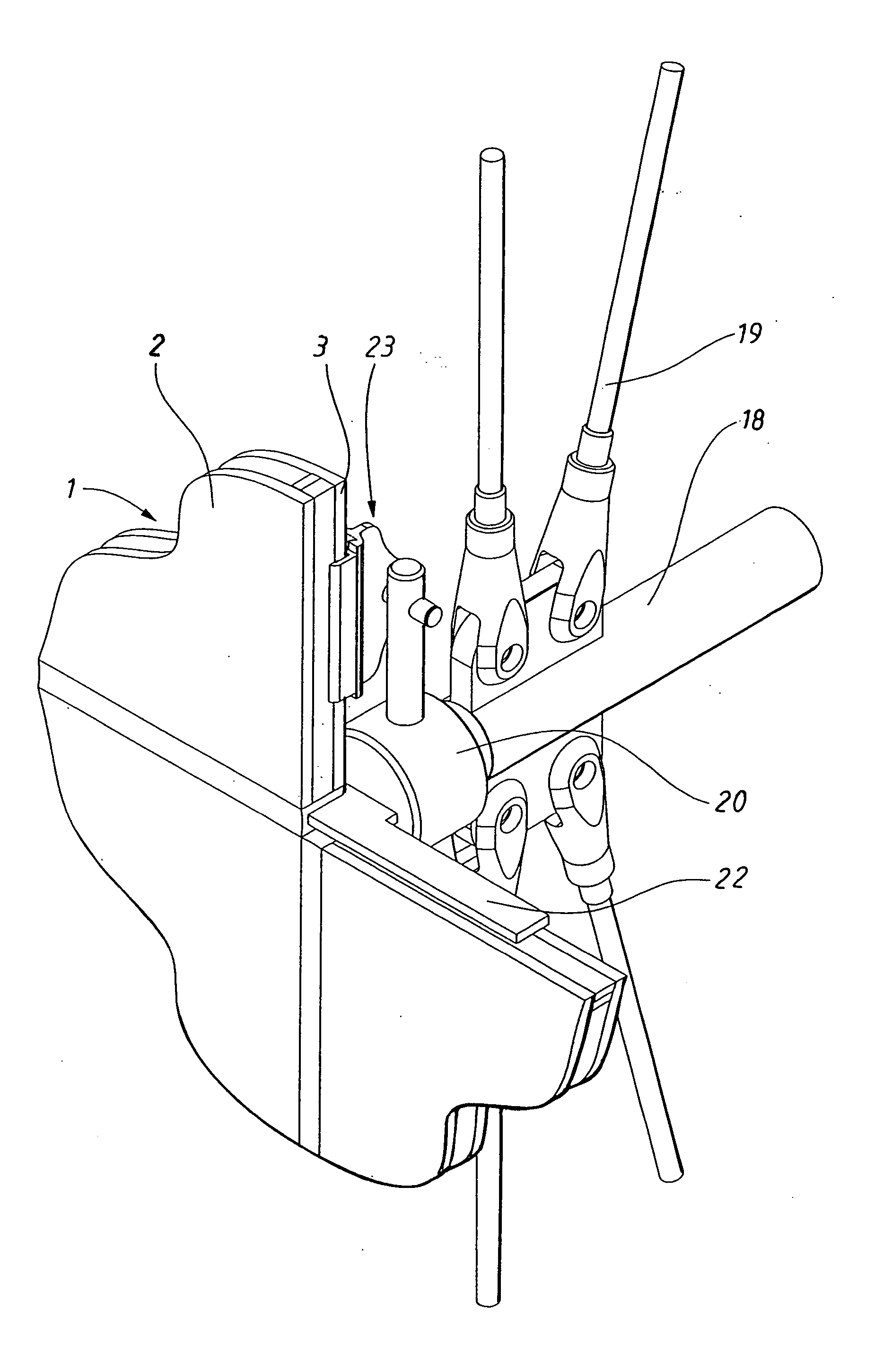
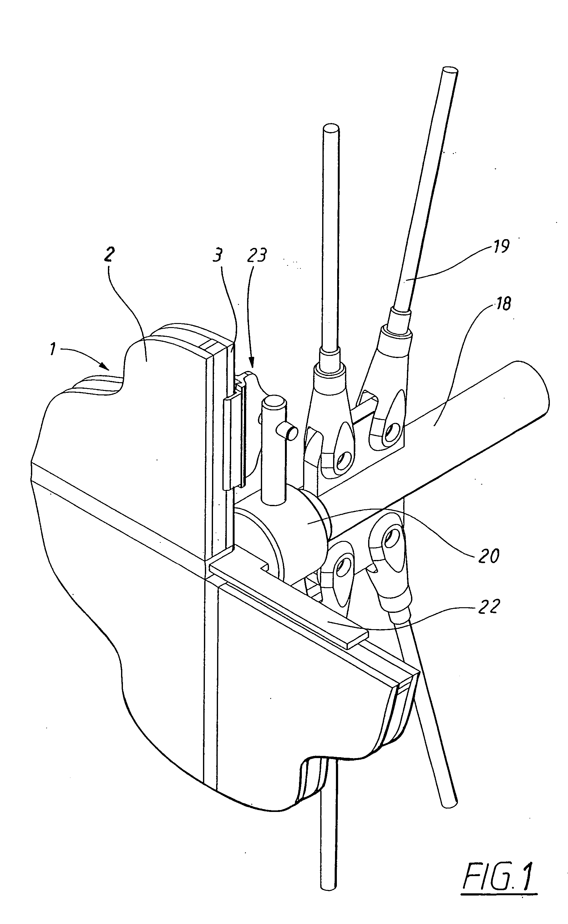
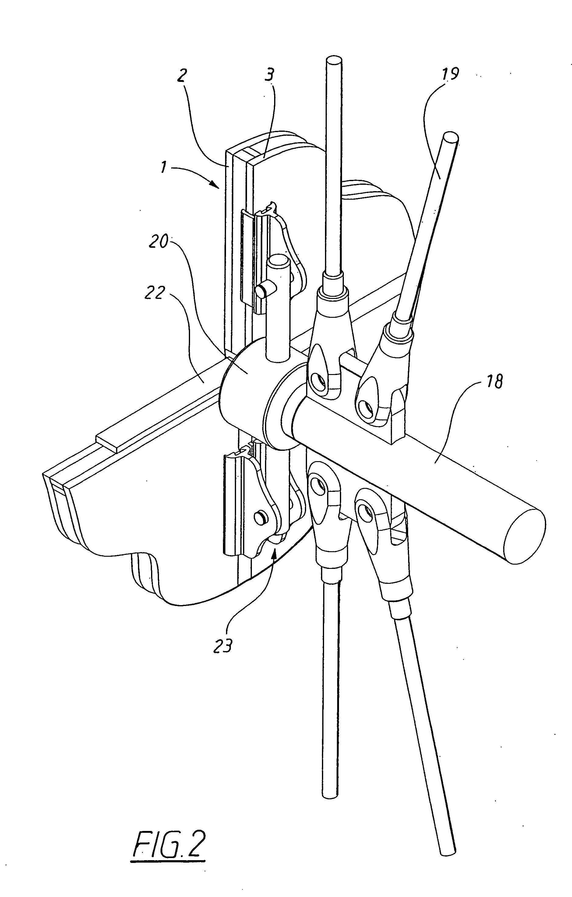
[0017] The glazing system according to the invention for mounting building facades or glazings and roofs to spaces are primarily assembled by sheet-shaped module elements, in the illustrated figures designated with 1. Each module element comprises an outer sheet 2 and an inner sheet 3. They have thus the form of a sealed glazing unit. Preferably, the surface of the module elements 1 is rectangular or square and mounted on a building frame with a horizontal lower and upper edge and with vertical side edges. The elements are mounted with their edges beside each other, such that the larger surface that is required in order to form a facade or a glazing part, is formed. Even if it is assumed here that the elements are perpendicular, when building glazing systems according to the invention, it is not excluded that elements of other forms may be used, for example triangular or polygonal, either solely or in combination with perpendicular elements. In a facade or a glazing there may also b...


PUM


Abstract

Glazing system for buildings, comprising a number of module elements (1) arranged to be joined to parts that are part of a building without intermediate framework. The elements comprises a glass sheet (3) each, which is supported by the frame (18) of the building, by means of supporting elements (22) and is retained in an intended position by means of retaining devices (23) supported by the frame, which retaining devices (23) each one is arranged to be joined with the sheet by means of attachment elements (12). The attachment elements (12) are arranged with organs (38) for coupling the attachment elements to coupling organs (43) on the respective retaining device (23), before being mounted on the building frame, the module elements (1) are arranged with the attachment elements (12) attached, which thus form a handling protection against damages of the edge of the sheet (3). The retaining devices (23) are at the mounting attached to the frame (18) with their coupling organs (43) in positions corresponding to those positions that the coupling organs (38) of the attachment elements (12) of the respective sheet (3) will take when the sheet is positioned in its intended position. The module elements (1) may thus be mounted from the inside of the building part by connecting the coupling organs of the retaining devices with the coupling organs (38) of the respective attachment element (12).

Description

TECHNICAL FIELD [0001] The present invention relates to glazing systems at which glass elements meet each other edge to edge without any visible framing. Such glazing is sometimes referred to as structure glazing. BACKGROUND OF THE INVENTION [0002] At the above mentioned glazing systems, the glass elements may be in the form of single glass or in the form of sealed glazing units with two or more glass sheets that are stuck to each other with air or gas-filled spaces. At a typical such arrangement with sealed glazing units, the glass elements are constituted by an inner and an outer glass sheet, where the latter shall form the facade surface of the glazing. The two glass sheets are joined together with an intermediate frame, which, at least at the side edges of the glass elements, is indented from these edges, at which a groove from the respective edge thereby is formed. When the glass elements are mounted with the edges of their outer glass sheets adjacent to each other, there shall...

Claims


Application Information

Patent Timeline
IPC IPC(8): E04B2/88E06B1/38E06B3/54
CPCE04B2/885E06B3/5445E06B3/5427E06B1/38
Inventor LUNDGREN
Owner LUNDGREN
Learn More