Elevator door drive device

Active Publication Date: 2005-06-16
INVENTIO AG
View PDF3 Cites 20 Cited by
  • Summary
  • Abstract
  • Description
  • Claims
  • Application Information

AI Technical Summary

Benefits of technology

[0009] The present invention creates equipment of the afore-described kind which avoids the stated disadvantages, i.e. in which the adjusting ele

Problems solved by technology

This setting usually produces, apart from correct movem

Method used


Image

  • Elevator door drive device
  • Elevator door drive device
  • Elevator door drive device

Examples


Embodiment Construction

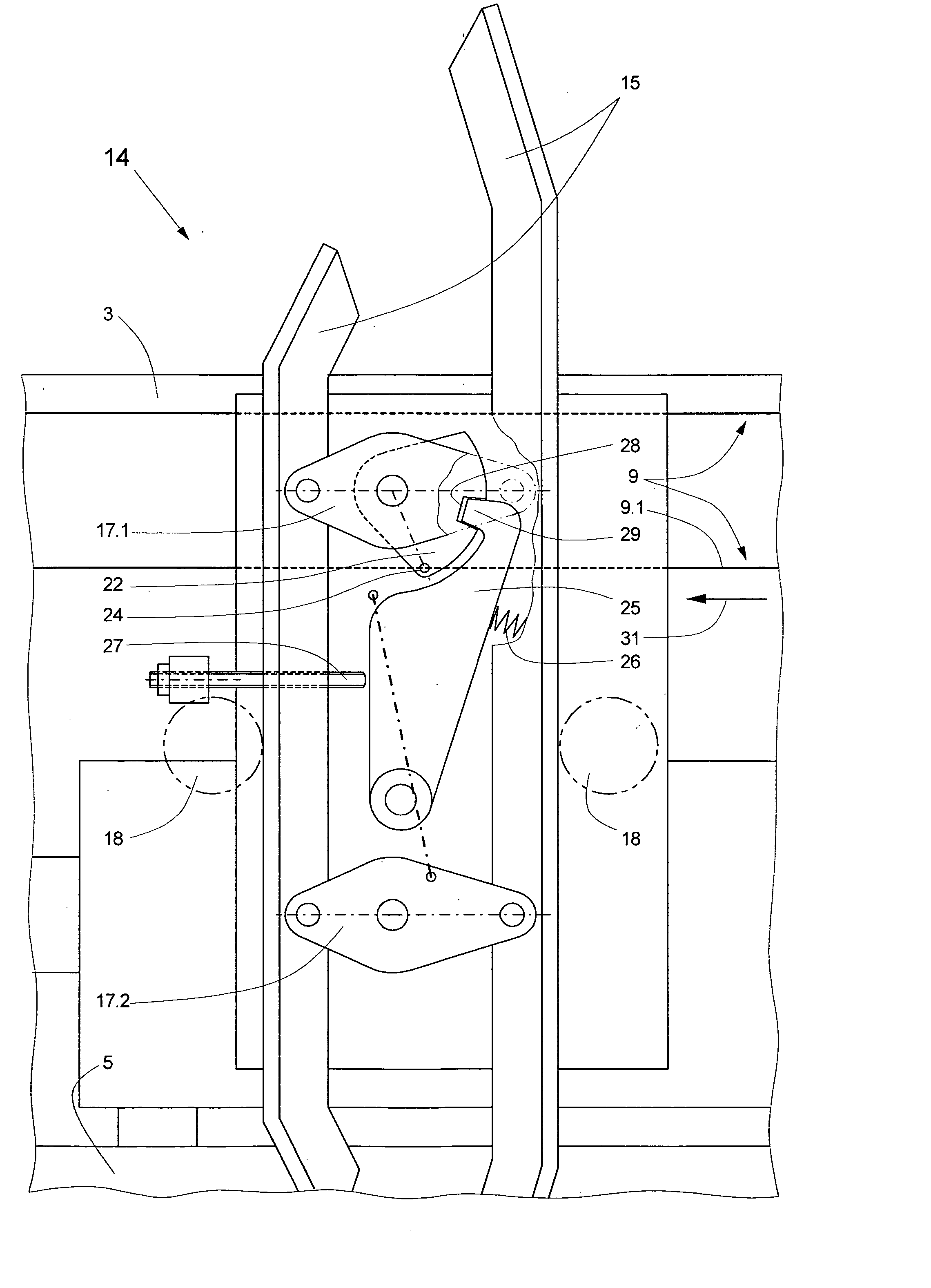
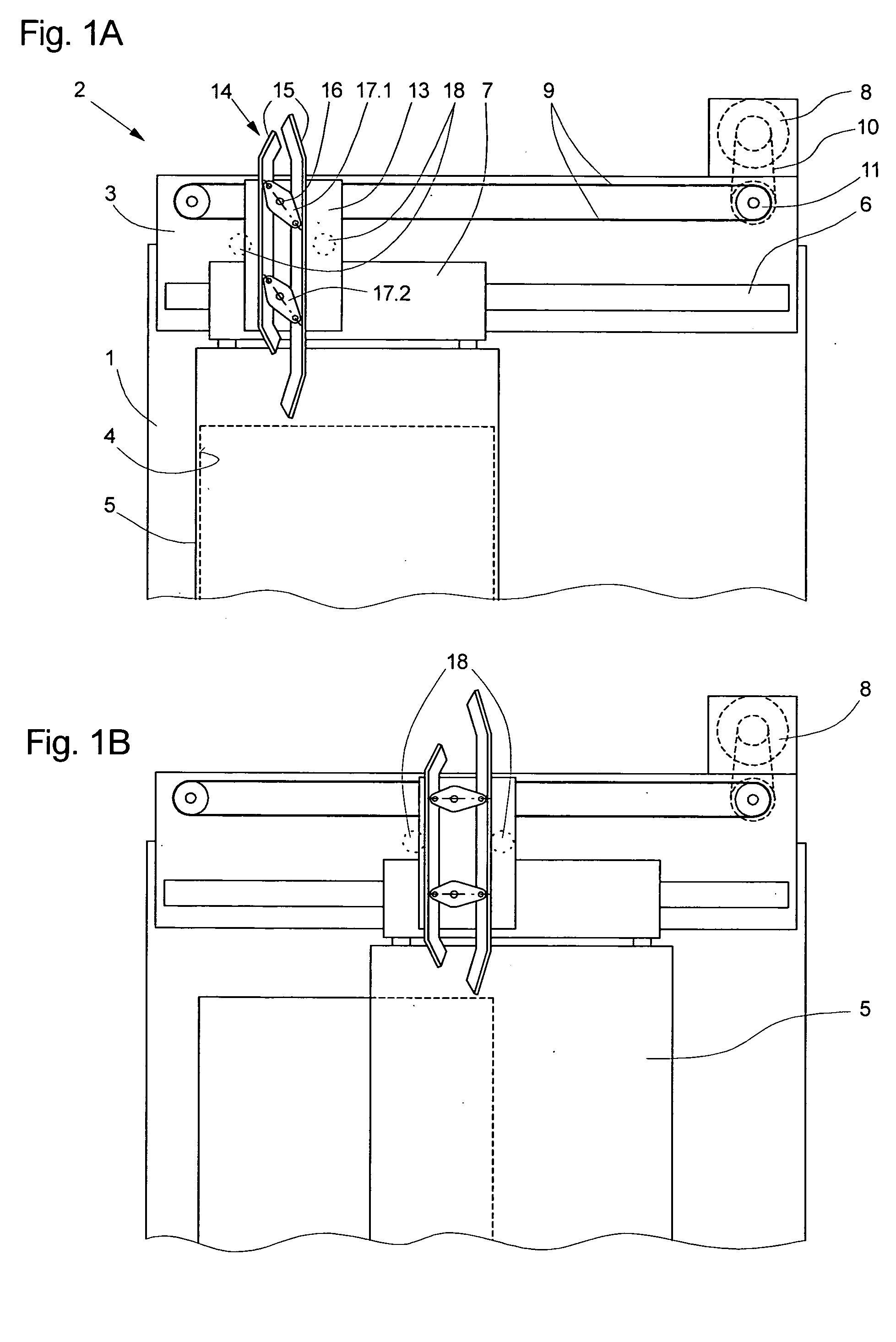
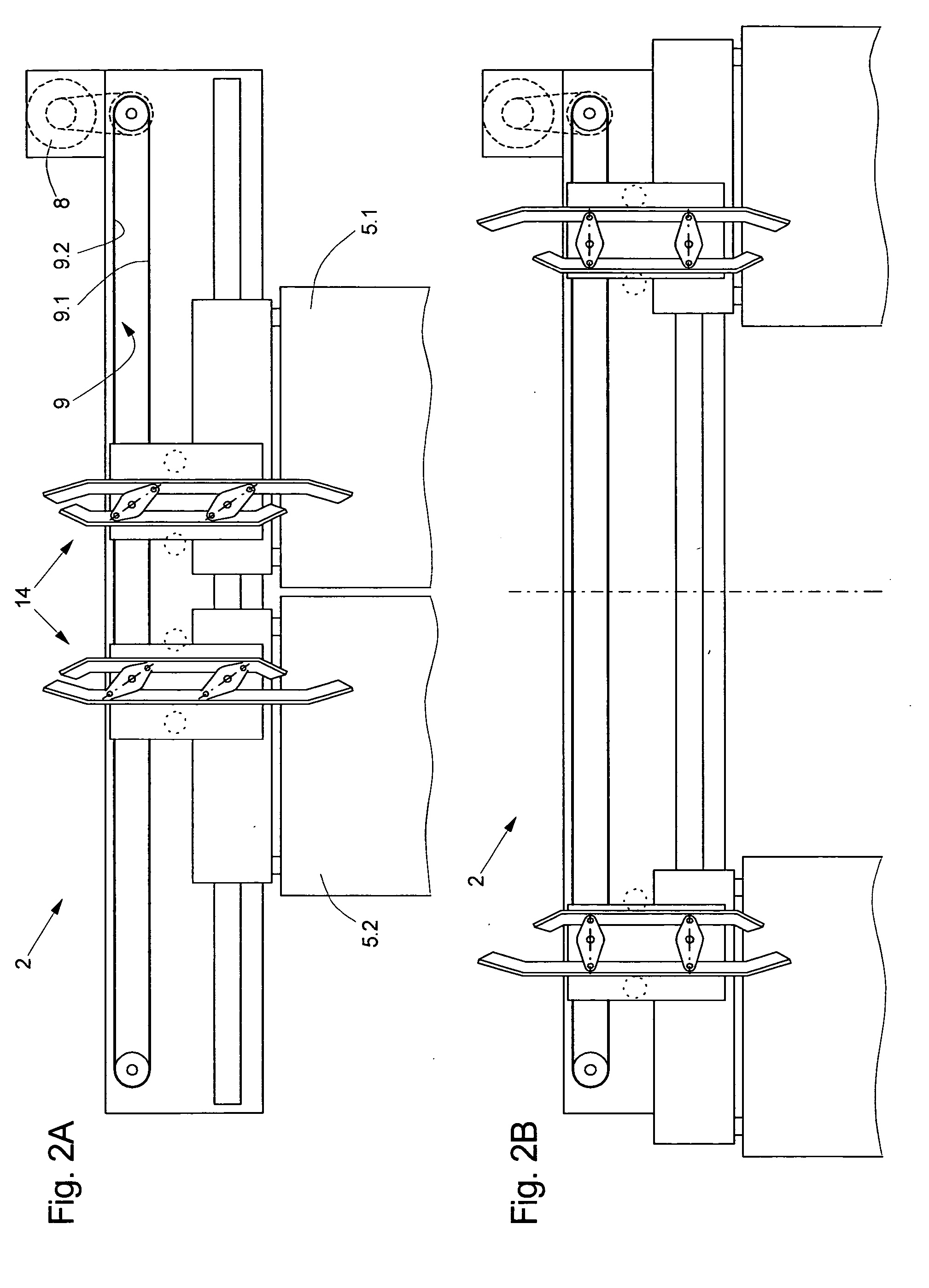
[0028]FIGS. 1A and 1B schematically show an elevator door drive device 2, which is mounted at an elevator car 1, for a laterally closing single-leaf door. The elevator car 1 with a door opening 4, which is closable by a car door leaf 5, can be seen. The elevator door drive device 2 is installed on a door support 3 fastened to the elevator car 1. The door leaf 5 is fastened to a suspension carriage 7 which is laterally displaceable along a guide rail 6, fixed to the door support and which is moved between a door leaf opening setting and a door leaf closed setting by a drive unit 8 via a linearly acting, circulating drive means 9. An electric motor, which drives a drive pulley 11 of the linearly acting drive means 9 at a regulated or an unregulated rotational speed by way of a transmission 10, can serve as the drive unit 8. The linearly acting drive means 9 can be a cogged belt, a flat belt, a V-belt or also a roller chain.

[0029] A base plate 13, on which a coupling mechanism 14 for ...


PUM


Abstract

An elevator door drive device, which opens and closes at least one car door leaf and a corresponding shaft door leaf, includes a coupling mechanism mounted at the car door leaf for transmitting the car door leaf movement to the shaft door leaf with two parallel entraining runners mounted on pivotable adjusting elements. The spacing between the runners is adjustable and a drive unit transmits closing and opening movements to the car door leaf by way of a drive apparatus that leads the entraining runners to a coupling element at the shaft door leaf before the start of the opening movement and moves them away from the coupling element after the end of the closing movement. The pivotable adjusting elements, during opening or closing the door leaf are blocked by means of a catch acting in both pivot directions.

Description

BACKGROUND OF THE INVENTION [0001] The present invention relates to an elevator door drive device for opening and closing at least one car door leaf and at least one associated shaft door leaf of an elevator. [0002] The present invention further relates to the problem of transmitting the opening and closing movement, which is produced by a car door drive, from at least one car door leaf to the associated shaft door leaf. [0003] A door drive device with a coupling mechanism for coupling a card door leaf with an associated shaft door leaf has become known from European Patent Specification EP 0 332 841. The coupling mechanism comprises two entraining runners which are oriented to be parallel to the travel direction of the elevator car and which are adjustable in their mutual spacing by a parallelogram guide with two adjusting elements each pivotable about a respective pivot axis. If the elevator car is correctly disposed at a floor level, the two entraining runners lie between two cou...

Claims


Application Information

Patent Timeline
IPC IPC(8): B66B13/12B66B13/30
CPCB66B13/12
Inventor BISANG, DANIELLUTOLF, JURGENTHIELOW, FRANK
Owner INVENTIO AG
Why Eureka
Try Eureka