
Structural assemblies and preforms therefor formed by friction welding

Inactive Publication Date: 2005-06-16
THE BOEING CO
View PDF43 Cites 60 Cited by
  • Summary
  • Abstract
  • Description
  • Claims
  • Application Information

AI Technical Summary

Benefits of technology

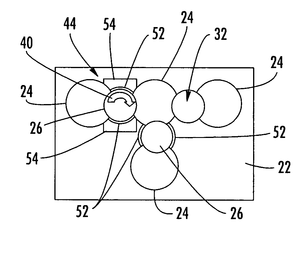
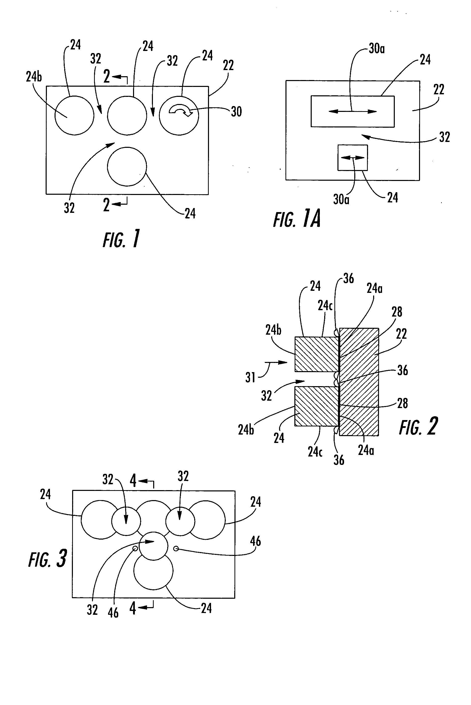
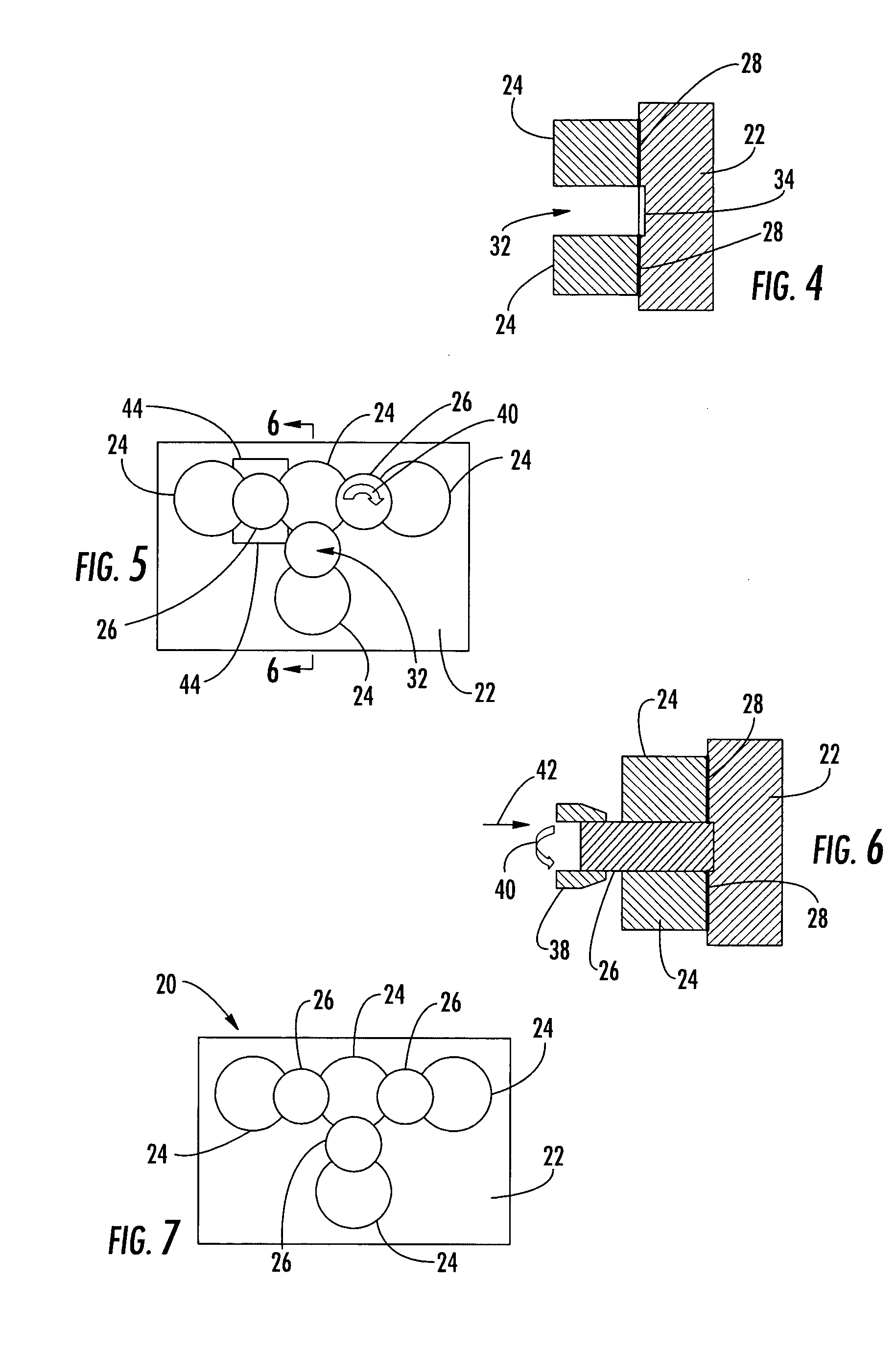
[0006] The present invention provides a frictionally welded preform and method for forming a structural assembly. The method includes welding structural members to a base member and subsequently providing a connection material to join the structural members. The resulting preform can be formed with dimensions and a configuration that approximate the dimensions and configuration of the structural assembly. Thus, the structural assembly can be formed by joining multiple members that are generally smaller than the finished assembly. For example, the preform can be formed by a device that is configured to rotary friction weld or friction stir weld relatively small structural members, regardless of the size of the finished structural assembly. The assembly can be formed from the preform with a reduced amount of machining or other processing, thereby saving time, materials, and energy.

Problems solved by technology

Such assembling of individual members may be necessary to form devices that are too large or too complicated to be formed by conventional manufacturing methods.
For example, such factors as casting sizes, forging sizes, available plate and block sizes, and the like can limit the size and geometry of the structural members that can be manufactured.
The fasteners and the overlap of material result in an increase in weight of the joint and the structural assembly.
However, the formation of conventional weld joints, such as by arc or electron beam welding, can result in undesirable dimensional changes in the structural members.
Welding can also introduce porosity or other discontinuities into the structural members or otherwise cause unwanted changes to the material properties of the structural members.
However, each of these conventional friction welding techniques is limited by the dimensions of the structural members and / or the joints to be formed.
Because of the difficulty of moving large structural members, it can be impossible or impractical to join some structural members by these techniques.

Method used


Image

  • Structural assemblies and preforms therefor formed by friction welding
  • Structural assemblies and preforms therefor formed by friction welding
  • Structural assemblies and preforms therefor formed by friction welding

Examples


Embodiment Construction

[0028] The present invention now will be described more fully hereinafter with reference to the accompanying drawings, in which preferred embodiments of the invention are shown. This invention may, however, be embodied in many different forms and should not be construed as limited to the embodiments set forth herein; rather, these embodiments are provided so that this disclosure will be thorough and complete, and will fully convey the scope of the invention to those skilled in the art. Like numbers refer to like elements throughout.

[0029] Referring to the drawings and, in particular, to FIGS. 8 and 9, there is illustrated a structural assembly 10 according to one embodiment of the present invention. The illustrated structural assembly 10 is a T-section flange, which includes a flange portion 12, a stiffener portion 14, and a web portion 16, each of which can be orthogonal to the other portions. The structural assemblies formed according to the present invention can be formed from p...


PUM

PropertyMeasurementUnit
Shapeaaaaaaaaaa
Circumferenceaaaaaaaaaa
Frictionaaaaaaaaaa

Abstract

A preform and method for forming a structural assembly are provided. The preform can be formed by friction welding structural members to a base member and subsequently providing a connection material to join the structural members. The resulting preform can be formed with dimensions and a configuration that approximate the dimensions and configuration of the structural assembly. Thus, the structural assembly can be formed by joining multiple members that are generally smaller than the finished assembly.

Description

FIELD OF THE INVENTION [0001] This invention relates to friction welding and, more specifically, to friction welding a plurality of structural members to form a preform or a structural assembly. BACKGROUND OF THE INVENTION [0002] Structural devices are often formed as assemblies of a number of smaller structural members. Such assembling of individual members may be necessary to form devices that are too large or too complicated to be formed by conventional manufacturing methods. For example, such factors as casting sizes, forging sizes, available plate and block sizes, and the like can limit the size and geometry of the structural members that can be manufactured. To form larger or more complex devices, the structural members are typically assembled by joining the individual structural members using a variety of known joining techniques including, for example, mechanical fastening or welding. [0003] Joints formed by mechanical fasteners such as rivets, screws, and bolts typically re...

Claims


Application Information

Patent Timeline
IPC IPC(8): B23K20/12
CPCB23K20/12B23K20/1205Y10T428/12B23K20/129B23K20/1215
Inventor SLATTERY, KEVIN T.YOUNG, KEITH A.
Owner THE BOEING CO
Features
  • Generate Ideas
  • Intellectual Property
  • Life Sciences
  • Materials
  • Tech Scout
  • Unparalleled Data Quality
  • Higher Quality Content
  • 60% Fewer Hallucinations
Learn More