Battery charging method

Active Publication Date: 2005-06-16
SANYO ELECTRIC CO LTD
View PDF3 Cites 89 Cited by
  • Summary
  • Abstract
  • Description
  • Claims
  • Application Information

AI Technical Summary

Benefits of technology

[0013] In the charging method above, a delay time is provided to determine whether any battery voltage has exceeded the prescribed voltage. If battery voltage still exceeds the prescribed voltage even after the delay time has elapsed, then t

Problems solved by technology

However, when batteries are charged by the method described above, there is a drawback that the voltages of all batteries cannot be uniformly aligned.
As a result, voltages of those batteries which were

Method used


Image

  • Battery charging method
  • Battery charging method
  • Battery charging method

Examples


Embodiment Construction

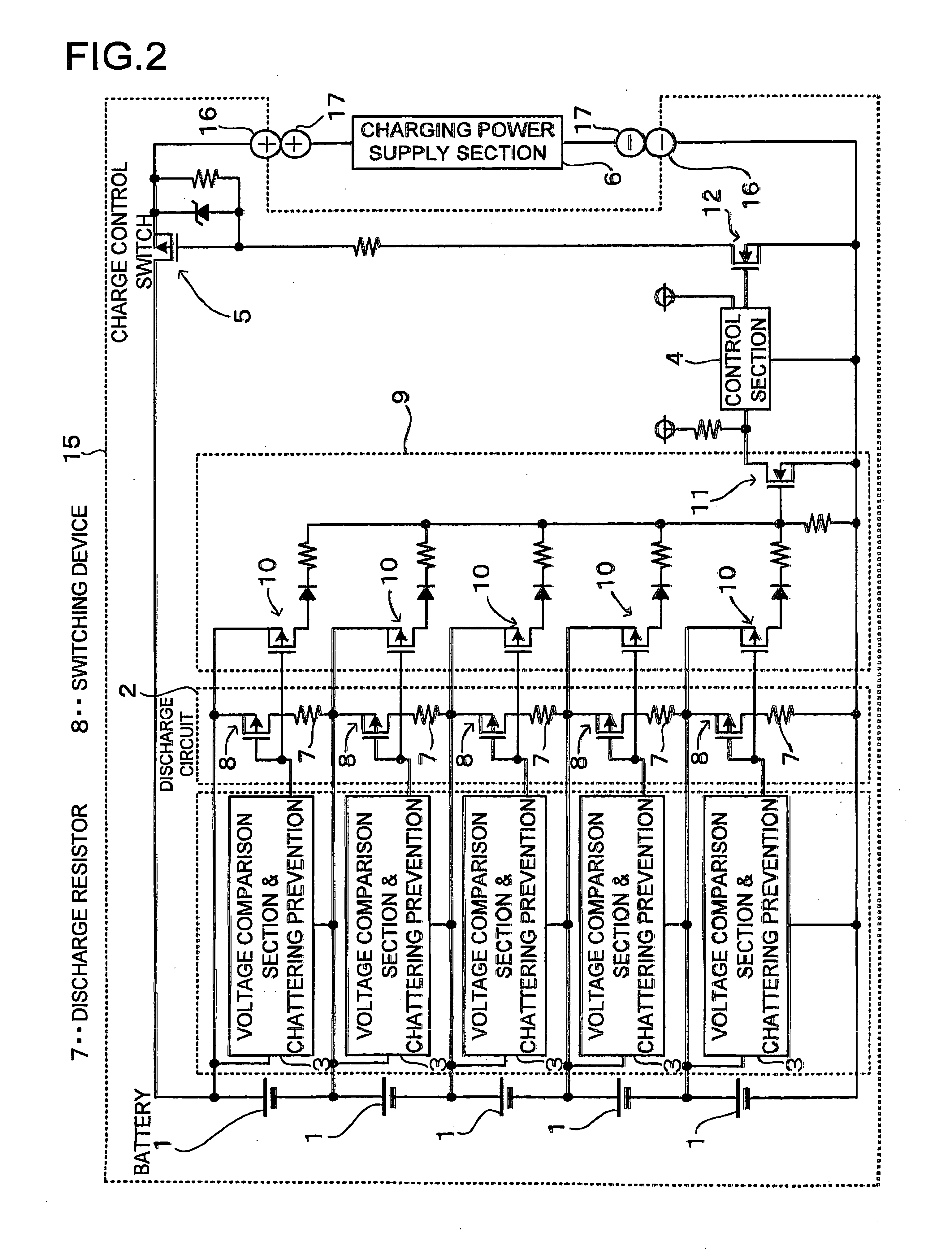
[0020]FIG. 2 shows a charging circuit including a voltage balancing circuit used in the charging method of the present invention. This charging circuit including voltage balancing is housed in a battery pack 15. The charging circuit with voltage balancing charges a plurality of rechargeable batteries 1 connected in series. The rechargeable batteries 1 are lithium ion batteries. However, the rechargeable batteries can be any batteries that can be recharged, such as nickel hydrogen batteries or nickel cadmium batteries instead of lithium ion batteries.

[0021] The battery pack 15 attaches to a charging power supply, section 6 in a detachable manner with its positive and negative battery output terminals 16 in electrical contact With positive and negative charging terminals 17 of the charging power supply section 8, Alternatively, instead of the detachable battery pack arrangement, it can also be configured as a battery pack internal to a piece of electrical equipment (not illustrated)....


PUM


Abstract

The battery charging method detects the voltage of each series connected battery, discharges batteries with voltage exceeding a prescribed voltage, and charges a plurality of batteries while maintaining cell balance. This charging method detects the voltage of each battery being charged and if any battery voltage exceeds the prescribed voltage, only the battery that exceeds the prescribed voltage is discharged, after a specified charging time, until its voltage drops to the prescribed voltage. Batteries that do not exceed the prescribed voltage are not discharged, and thereby all batteries are charged while balancing their voltages.

Description

[0001] This Invention relates to a method of charging batteries connected in series, and in particular to method which charges while balancing the voltage of each battery. [0002] Battery packs with a plurality of batteries connected in series are used in various applications. In particular, since output voltage can be increased by increasing the number of batteries connected in series, this type of battery pack is suitable for applications requiring large output. However, when many series connected batteries are charged, they gradually become unbalanced even though the same current flows in all batteries. This is because electrical characteristics and environmental conditions during charging and discharging cannot be maintained uniformly over all batteries (e.g. temperature variation). There is a strong tendency far a battery, which has reduced capacity, to over-charge or over-discharge relative to other batteries when connected in series. This is directly related to an observable r...

Claims


Application Information

Patent Timeline
IPC IPC(8): H01M10/44H02J7/02H02H7/18H02J7/00
CPCH02J7/0016Y02E60/10H01M10/44H02J7/04
Inventor YAMAMOTO, HIROYOSHIYAMAGUCHI, MASAOTAMAI, MIKITAKA
Owner SANYO ELECTRIC CO LTD
Why Eureka
Try Eureka