Image-taking apparatus and image-taking system

a technology of image-taking apparatus and image-taking system, which is applied in the direction of television system, mechanical vibration actuation of burglar alarm, instruments, etc., can solve the problems of narrow monitoring range, insufficient surveillance camera, and inability to detect a change in the filmed obj

Inactive Publication Date: 2005-06-16
CANON KK
View PDF6 Cites 115 Cited by
  • Summary
  • Abstract
  • Description
  • Claims
  • Application Information

AI Technical Summary

Benefits of technology

[0012] An image-taking apparatus according to one aspect of the present invention comprises an image-pickup element having a plurality of pixels; a control section selectively performing a first image-taking operation using the image-pickup element or a second image-taking operation at a higher pixel number or a lower frame rate than for the first image-taking operation; and a detecting

Problems solved by technology

However, in this configuration, the change of the filmed object is judged based on the change of the image data of the taken images, so that it is not possible to detect a change in the filmed object that is r

Method used


Image

  • Image-taking apparatus and image-taking system
  • Image-taking apparatus and image-taking system
  • Image-taking apparatus and image-taking system

Examples


embodiment 1

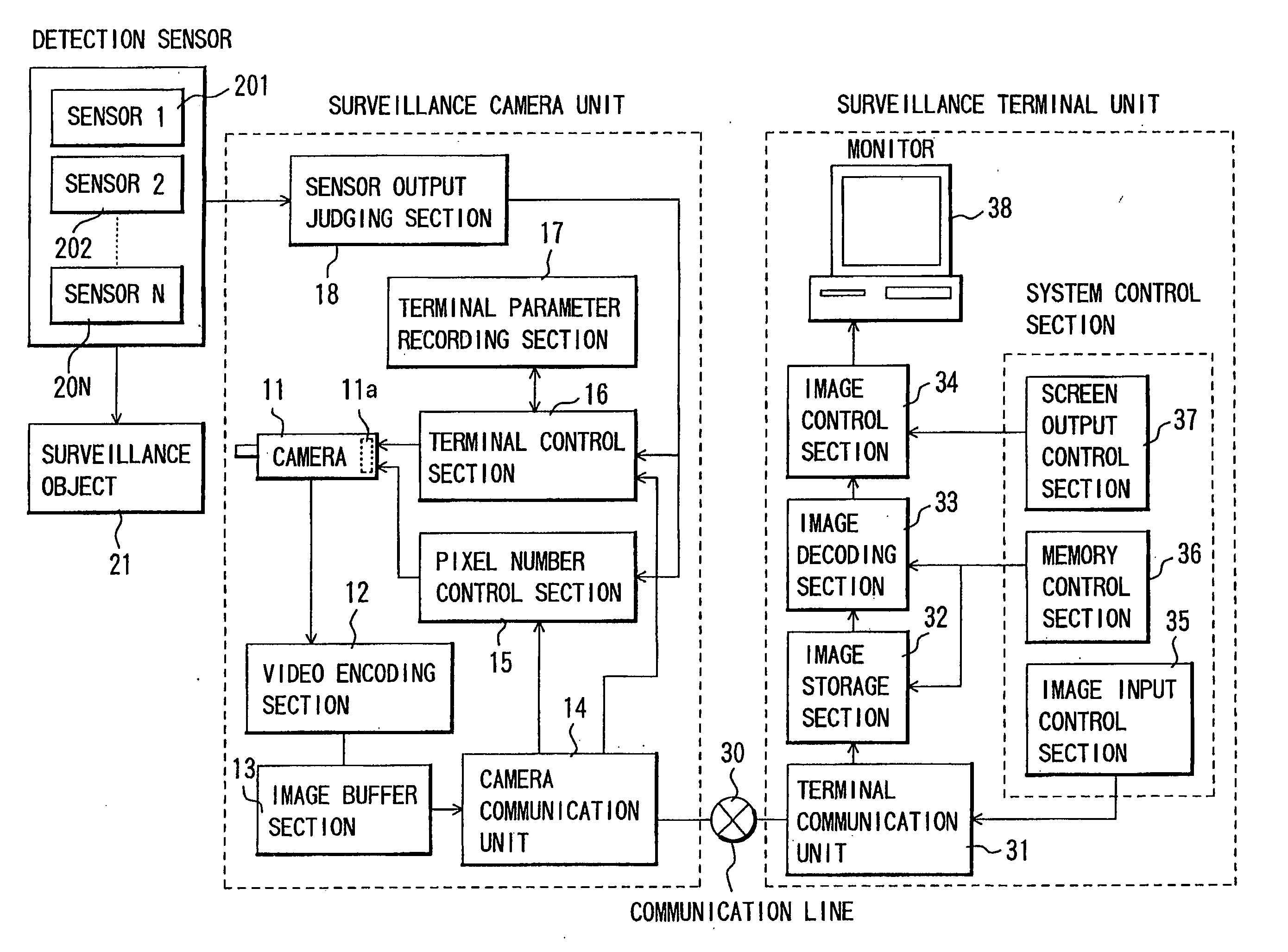
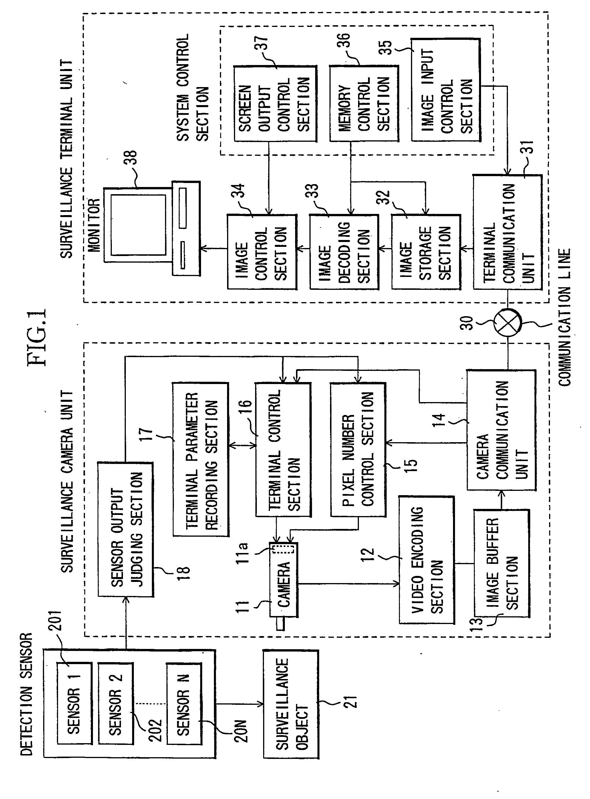
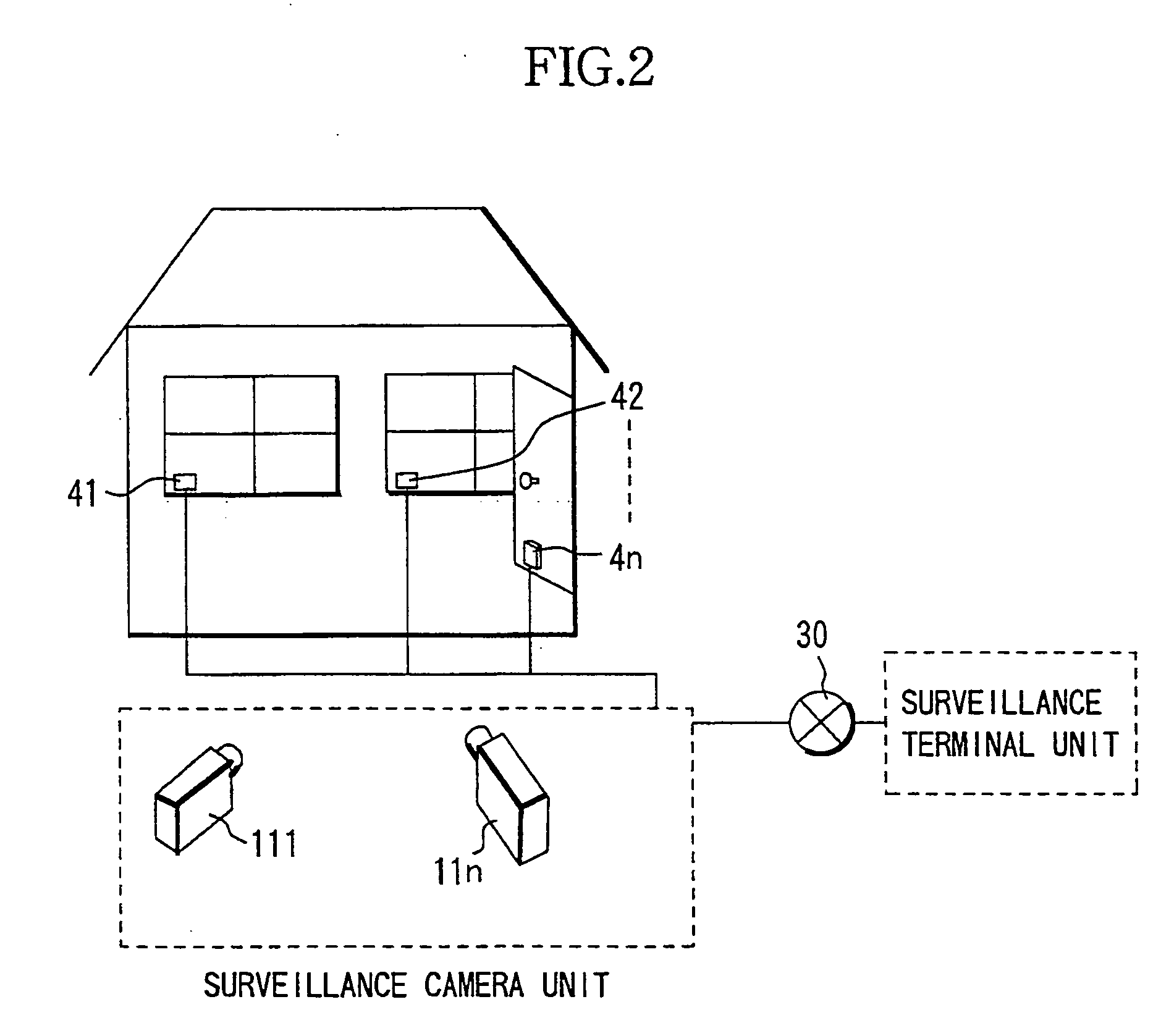
[0046] Using FIGS. 1 and 2, the following is an explanation of Embodiment 1 of the present invention. This embodiment relates to a surveillance camera system with the purpose of detecting intruders, in which vibration sensors are attached to the doors and windows of a house and detect whether the doors and windows are open or closed. If an applied vibration level exceeds a predetermined value, high-resolution image-taking is performed. FIG. 2 is a diagrammatic view showing how vibration sensors 41 to 4n are attached to the door and windows of a house. The internal configuration of the surveillance camera unit and the surveillance terminal unit are not shown in FIG. 2, with the exception of the cameras.

[0047] If the vibration level detected with any of the vibration sensors 41 to 41n is applied for more than a predetermined time or exceeds a predetermined level, then the sensor output judging section 18 judges that vibrations are applied because someone is trying to break into the h...

embodiment 2

[0061] Referring to FIGS. 1 and 4, the following is an explanation of Embodiment 2 of the present invention.

[0062] In Embodiment 2, a plurality of microphones 51 to 5n (detecting means) are placed in a street, and high-resolution image-taking is performed if a sound level exceeds a predetermined value. FIG. 4 is a diagrammatic view showing how a plurality of cameras are arranged on a street, such as a busy main street, and images of the street are taken. The microphones 51 to 5n have directionality, and the sound from a plurality of directions can be picked up using the plurality of microphones.

[0063] The sensor output judging section 18 judges whether the sound level of the sound that is picked up with the microphones 51 to 5n exceeds a predetermined value. If the sound level exceeds a predetermined value, then the sensor output judging section 18 judges from which direction the sound comes. It is possible to specify the direction of the sound if there are at least two directiona...

embodiment 3

[0073] Referring to FIGS. 1 and 6, the following is an explanation of Embodiment 3. Embodiment 3 relates to an image-taking apparatus for the purpose of monitoring the speed of vehicles, in which a speed sensor detecting the speed of vehicles is disposed beside a roadway. If the speed of a vehicle exceeds a predetermined speed, then high-resolution video images are automatically taken, which is useful to identify the vehicle holder. FIG. 6 is a diagrammatic view showing how the speed sensor for detecting vehicle speed is arranged beside the roadway and how it detects the speed of vehicles driving by.

[0074] When the sensor output Judging section 18 judges that the speed of a vehicle detected by the speed sensor 71 exceeds a predetermined speed, then the cameras 11a to 11n automatically take high-resolution video images of the vehicle driving at excessive speed. The taken video images are buffered as video data in the image buffer section 13.

[0075] Thus, by taking high-resolution im...


PUM


Abstract

An image-taking apparatus includes an image-pickup element having a plurality of pixels; a control section selectively performing a first image-taking operation using the image-pickup element or a second image-taking operation at a higher pixel number or a lower frame rate than for the first image-taking operation; and a detecting section detecting a state of an image-taking object. The control section performs the first image-taking operation when the state of the image-taking object detected by the detecting section is within a predetermined range, and performs the second image-taking operation when the state of the image-taking object detected by the detecting section is outside the predetermined range.

Description

BACKGROUND OF THE INVENTION [0001] 1. Field of the Invention [0002] The present invention relates to image-taking apparatuses and image-taking systems which are capable of sending video images over a network, such as a LAN or the Internet. [0003] 2. Description of Related Art [0004] In recent years, network cameras have been proposed which send images that have been taken with a camera via a communications network such as a LAN or the Internet to a surveillance terminal unit, such network cameras being used as a replacement for cameras storing video images on such media as tape or film. Cameras used as this kind of network cameras may be placed on busy streets, at locations where they cannot be reached by people, and the image data taken there may be sent via the communications network and displayed on a liquid crystal panel of a surveillance terminal unit. [0005] Moreover, network cameras have been proposed which allow such operations as panning, tilting or zooming of a remote came...

Claims


Application Information

Patent Timeline
IPC IPC(8): G08B13/16H04N5/225G08B13/196H04N5/228H04N7/18
CPCG08B13/1672G08B13/19641H04N7/181G08B13/19695H04N5/23206G08B13/19667H04N23/661
Inventor ISHINO, TOSHIKI
Owner CANON KK
Why Eureka
Try Eureka