Power source switching unit and power source management system comprising it

a power source switching unit and power source management technology, applied in non-electric variable control, process and machine control, instruments, etc., can solve the problems of increasing the size and cost of the whole electric power system, complicated wiring for networking and communication among the plurality of power source switching units, etc., to reduce the fuel consumption per output, prevent overload operation of the generator, and save costs

Inactive Publication Date: 2005-06-16
YANMAR CO LTD
View PDF6 Cites 38 Cited by
  • Summary
  • Abstract
  • Description
  • Claims
  • Application Information

AI Technical Summary

Benefits of technology

[0007] The power source switching units are provided corresponding respective load power groups so as to constitute a power source management system for the electric power system comprising the external power source and the power generation system having the engine and the generator driven by the engine. Accordingly, each of the power source switching units can detect the power source selected by its switching, and detect current and voltage of power (load power) supplied from the selected power source. The electric power management system is constituted by the existing mechanism for controlling the electric power system, thereby saving costs and ensuring its compactness.
[0009] The control system of the power generation system comprises means for receiving the data transmitted from the power source management system, and image-displaying means for displaying the received data diagrammatically. Accordingly, each of the above-mentioned data can be collected by data storage means so as to enter the data into a device out of network with the power generation system. Especially, if the data are to be processed by a program different from the processing program stored in the control system or image-displaying means of the power generation system, the data-storage means can be used to enter the date into a computer storing the different processing program, thereby enabling various data processing for controlling power. Further, each of the above-mentioned data can be registered by data register means so as to enable a user at the place of the image-displaying means to check patterns of power supply and variation of electric energy. Especially, if a printer exists, the existing printer can mainly serve as means for checking the data and the diagrammatized data, so that, even if the image-displaying means comprises a possibly expensive liquid crystal display, the image-display means can be small-sized so as to save costs.
[0010] In the power source management system, each of the power source switching units comprises means for communicating with the other power source switching unit. Accordingly, each of the power source switching units commands drive control of the generator for rating its output, or for fully using its output depending on the switching of the power source switching units to select the generator power source. Furthermore, overload operation of the generators can be prevented.
[0011] In the power source management system, each of the power source switching units can serve as a master unit comprising: means for recognizing the selection of the power source and the supplied power to the corresponding power load group connected to the power source switching unit itself or each of the other power source switching units; and means for controlling a total value of power supplied of the electric power system to a level substantially equal to a rated value. Accordingly, almost all rated output of the generator is consumed by the power load groups, and the engine can drive with minimized fuel consumption per output.

Problems solved by technology

However, addition of such means as to detect power values to the respective power load groups for checking whether the generator or the external power source supplies power to each of the power load groups increases the whole electric power system in size and cost.
However, the wiring is complicated for the networking and communication among the plurality of power source switching units.

Method used


Image

  • Power source switching unit and power source management system comprising it
  • Power source switching unit and power source management system comprising it
  • Power source switching unit and power source management system comprising it

Examples


Embodiment Construction

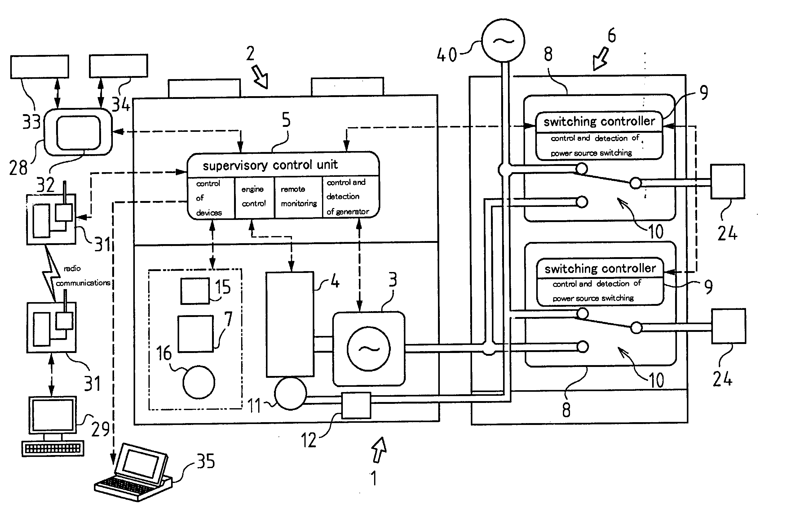
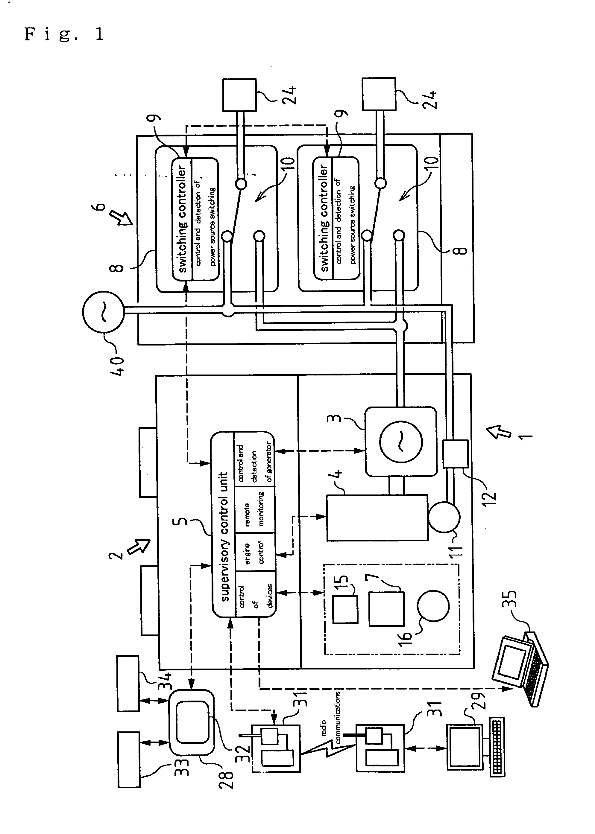
[0028] A mode for carrying out the invention will be explained on the basis of attached drawings. The present invention is applicable to any electric power system if it comprises a generator driven by an engine and power source switching units provided corresponding to each of power load groups, and the electric power system controls switching of supply power source for each power load group between the generator and an external power source corresponding to fluctuation of each power load group. Application of the present invention is not limited to an electric power system 1 of the present embodiment. For example, the present invention may be applied to a cogeneration system using a drive source of a generator as a heat source.

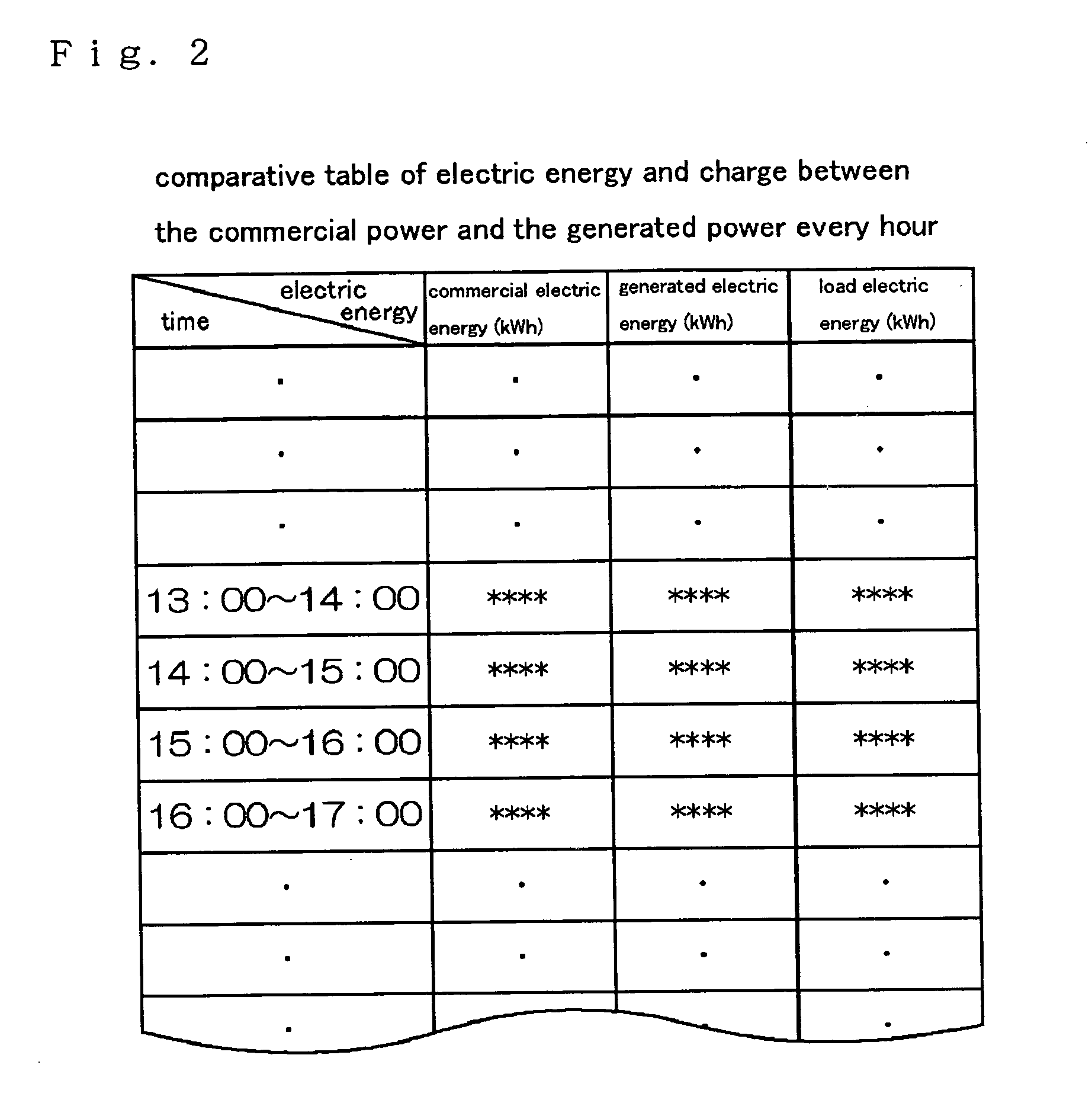
[0029] Power generated by the power generation system may be externally supplied as commercial power as well as that of the external power source. However, in the present embodiment, the power generated by the electric power system is not regarded as commerc...


PUM


Abstract

Each power source switching unit (8) of a electric power system (1) constituted of a power operating system having a power generator (3) driven by an external power source (40) and an engine (4) is constituted of a means for sensing information on a selected power source and supply power in time series, calculating a supply power quantity every power source on the basis of sense data, and storing these sensing and calculated data. This power source switching unit (8), disposed every power load group, comprises a means for communication with another power source switching unit (8). A power source management system, constituted of the power source switching unit (8), comprises a means for transmitting the sensed data or calculated data of each power source switching unit (8) to the control system of the power generating system, a means for receiving data transmitted from the power source management system, and an image display means for displaying the received data by graphing.

Description

TECHNICAL FIELD OF THE INVENTION [0001] The present invention relates to a electric power system comprising a generator driven by an engine and power source switching units provided to respective power load groups, wherein each of the power source switching units controls its switching for alternatively selecting either the generator or the external power source as a power source supplying power to the corresponding power load group. BACKGROUND ART [0002] Conventionally, there is a well-known electric power system comprising: a power generation system having a generator driven by an engine; and a power source selector which is switched to alternatively select either an external power source or the generator as a power source supplied to each of power load groups. [0003] The power source selector has power source switching units provided corresponding to the respective power load groups. Each of the switching units has means for detecting data concerning a value of electric power at ...

Claims


Application Information

Patent Timeline
Patent Type & Authority Applications(United States)
IPC IPC(8): H02J3/00H02J3/38H02J3/46H02J13/00
CPCH02J3/005H02J3/38H02J3/46H02J13/001H02J13/0062H02J13/0075Y02E40/72Y04S10/40Y04S40/124Y04S40/126Y02E60/7838Y02E60/7853Y04S10/12H02J13/00001H02J13/00016Y02E60/00Y04S20/221Y04S20/222Y02B70/30Y02B70/3225H02J3/007H02J13/00022Y02E40/70
Inventor HIBI, SHINJITOKIWA, MASAYOSHIFUJISAWA, TOSHINOBUKANEMOTO, TADATATSUGODA, YASUNORIFUKAE, MAMORUYOSHIMOTO, HIROSHI
Owner YANMAR CO LTD
Why Eureka
Try Eureka