
Light generating device that self centers within a lumen to render photodynamic therapy

Inactive Publication Date: 2005-06-16
LIGHT SCI CORP
View PDF30 Cites 5 Cited by
  • Summary
  • Abstract
  • Description
  • Claims
  • Application Information

AI Technical Summary

Benefits of technology

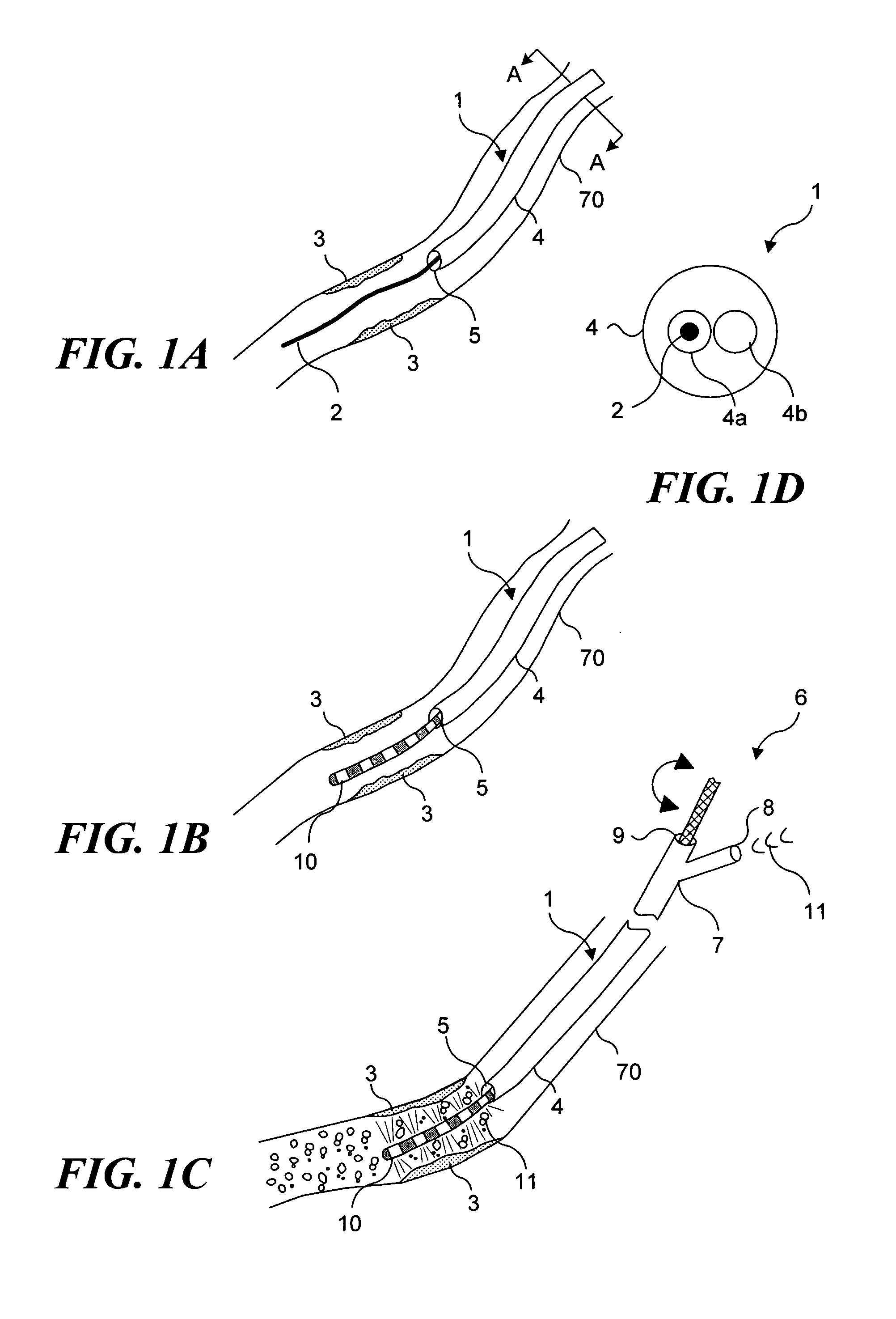
[0016] The embodiments described above are preferably used with a photoreactive agent that is introduced into the target area prior to the apparatus being introduced into the blood vessel. However, it will be understood that if desired, the apparatus can optionally include a lumen for delivering a photoreactive agent into the target area. Such an embodiment is likely to be particularly beneficial when uptake of the photoreactive agent into the target tissues is relatively rapid, so that the apparatus does not need to remain in the blood vessel for an extended period of time while the photoreactive agent is distributed into and absorbed by the target tissue.

Problems solved by technology

The light source that is used is selected based on the characteristics of a photoreactive agent with which the apparatus is intended to be used, since light of incorrect wavelengths or waveband will not cause the desired reaction by the photoreactive agent.
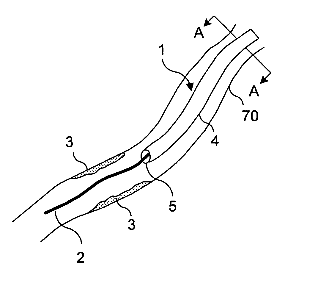
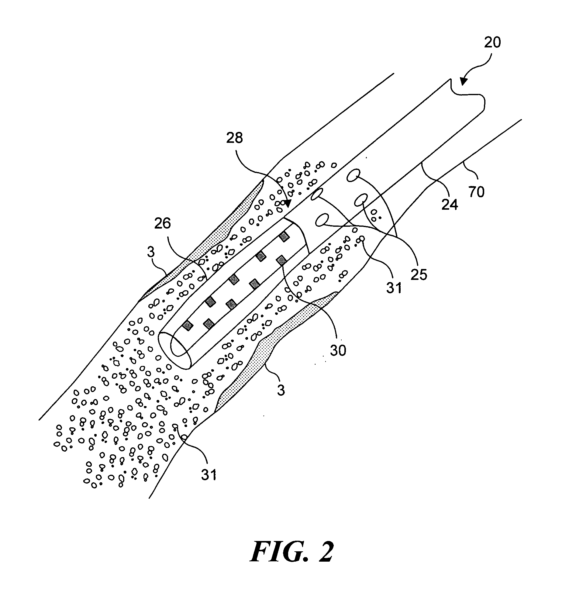
Displacing or occluding bodily fluids, such as blood, from a body lumen into which such a device is introduced, is important because the presence of such bodily fluids (in particular, the presence of blood) will likely interfere with the transmission of light (from a light source associated with the device) to a target area (generally a lesion in the wall of the lumen).
If light cannot reach the treatment area, the treatment will not be carried out.

Method used


Image

  • Light generating device that self centers within a lumen to render photodynamic therapy
  • Light generating device that self centers within a lumen to render photodynamic therapy
  • Light generating device that self centers within a lumen to render photodynamic therapy

Examples


Embodiment Construction

[0026] Unless otherwise defined, it should be understood that each technical and scientific term used herein and in the claims that follow is intended to be interpreted in a manner consistent with the meaning of that term as it would be understood by one of skill in the art to which this invention pertains. The drawings and disclosure of all patents and publications referred to herein are hereby specifically incorporated herein by reference. In the event that more than one definition is provided herein, the explicitly defined definition controls.

[0027] Various embodiments of light-generating devices that are able to center the device within a body lumen and optionally substantially preclude the flow of bodily fluid past a distal portion of the device, and a method for illumination and excitation of photoreactive agents in vessels or other body lumens (i.e., to administer PDT) are described herein. An objective of administering PDT with the invention may be either diagnostic, wherei...


PUM


Abstract

A light generating device for illuminating tissue adjacent to a body lumen while a distal end of the device is centered in the lumen, to render photodynamic therapy. The device can either occlude or displace bodily fluid, both without the use of a balloon. In one embodiment, a flushing lumen has a port adjacent to an array of light sources, to displace bodily fluid that might otherwise absorb light. Another embodiment employs a centering member that moves between a first position and a second position. The centering member centers the device in the lumen and preferably is formed of a shape memory material. In yet another embodiment, the device includes an outer sheath and an inner member that are independently positionable, enabling the centering member to be selectively positionable. The centering member can be non porous, such that the centering member also occludes fluid flow.

Description

RELATED APPLICATIONS [0001] This application is based on a prior copending provisional application, Ser. No. 60 / 485,858, filed on Jul. 8, 2003, the benefit of the filing date of which is hereby claimed under 35 U.S.C. §119(e), and is also a continuation-in-part of a prior copending application, Ser. No. 10 / 799,357, filed on Mar. 12, 2004, which itself is based on a prior copending provisional application, Ser. No. 60 / 455,069, filed on Mar. 14, 2003, the benefits of the filing dates of which are hereby claimed under 35 U.S.C. §119(e) and 35 U.S.C. §120.FIELD OF THE INVENTION [0002] The present invention generally relates to a method and apparatus for using light to diagnose and treat tissue, and more specifically, to a method and apparatus to treat or diagnose tissue accessible via a cavity, duct, vessel, or other lumen of a body, wherein the apparatus is able to center itself within the lumen, and to prevent blood flow in the vessel from interfering with light transmission to the ti...

Claims


Application Information

Patent Timeline
IPC IPC(8): A61BA61N5/06A61N5/067A61N5/10F21S2/00
CPCA61M2025/1047A61N5/0601A61N2005/1003A61N2005/0652A61N5/062
Inventor CHEN, JAMES C.GUO, ZIHONGLICHTTENEGGER, GARYSHINE, DAVID B.BURWELL, PHILLIP
Owner LIGHT SCI CORP
Learn More