
Locking spacer assembly for slotted turbine component

Inactive Publication Date: 2005-06-16
SIEMENS ENERGY INC
View PDF23 Cites 34 Cited by
  • Summary
  • Abstract
  • Description
  • Claims
  • Application Information

AI Technical Summary

Benefits of technology

[0007] Thus, one object according to aspects of the present invention is to provide a spacer assembly that facilitates installation and removal of the spacer assembly for construction and repair of turbine blade fans. It is another object of the invention to provide a spacer assembly that securely locks into place and is highly resistant to disassembly and dislodgement under high centrifugal forces during turbine operation. These and other objects according to aspects of the present invention are addressed below.

Problems solved by technology

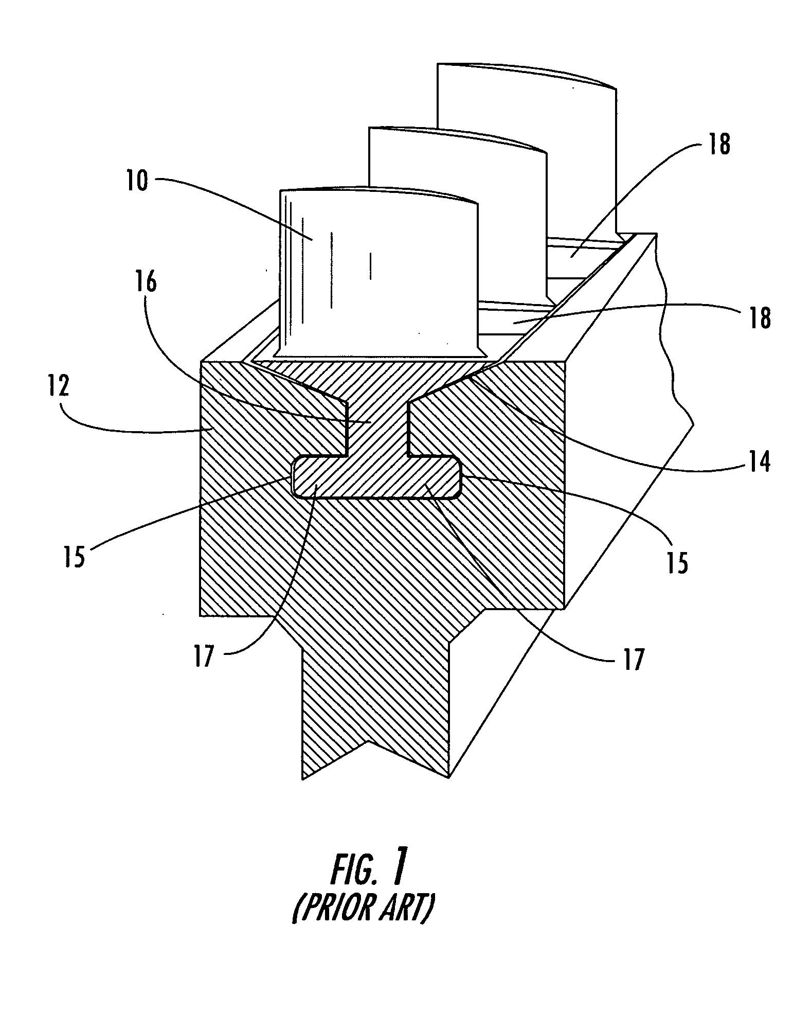
However, when the blade 10 and spacer 18 array is near complete installation, there is not sufficient space remaining in the slot 14 to permit insertion and rotation of the final spacer 18.
However, under the great centrifugal forces encountered during operation of the turbine, these multipart spacers can come apart and dislodge, causing extensive damage to the turbine engine.

Method used


Image

  • Locking spacer assembly for slotted turbine component
  • Locking spacer assembly for slotted turbine component
  • Locking spacer assembly for slotted turbine component

Examples


Embodiment Construction

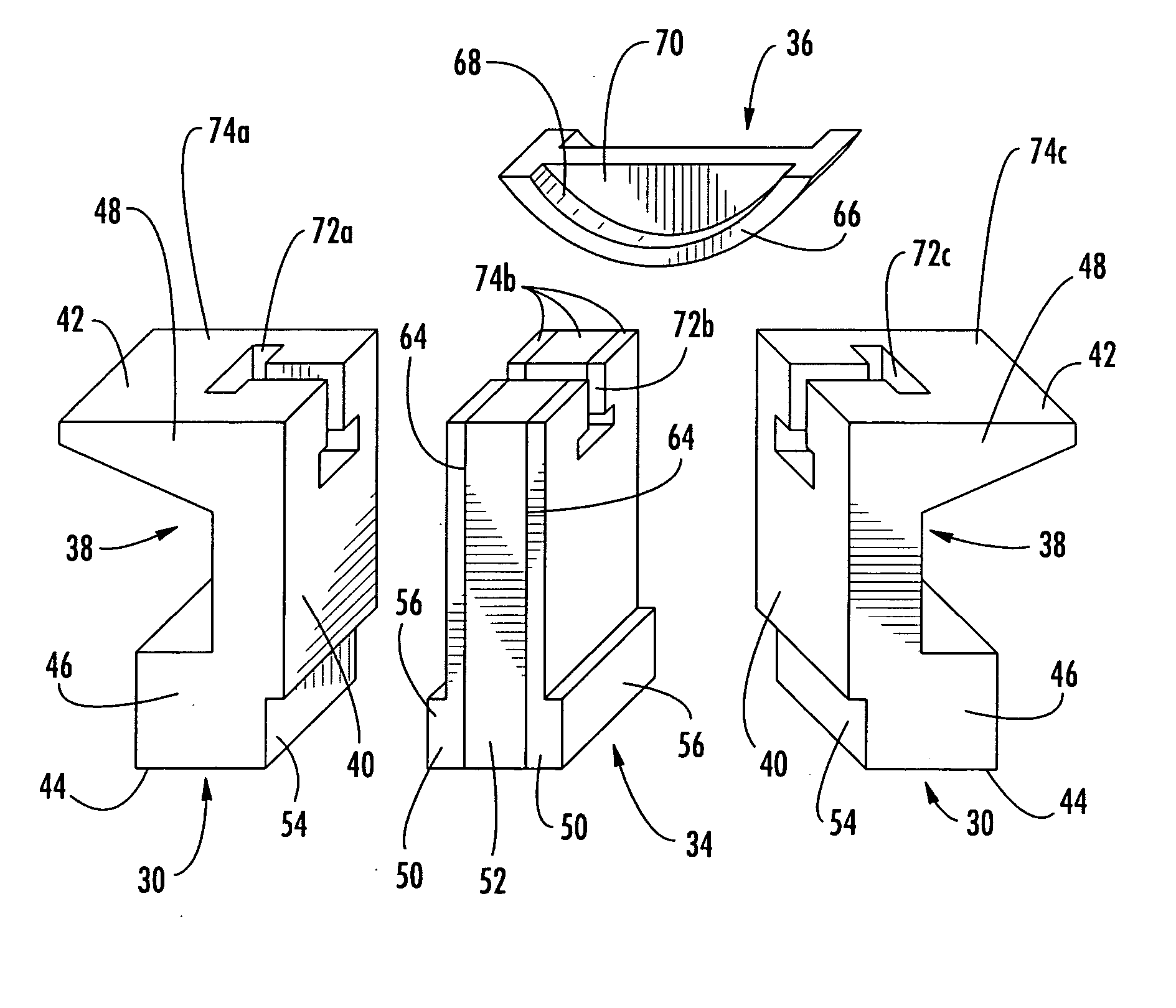
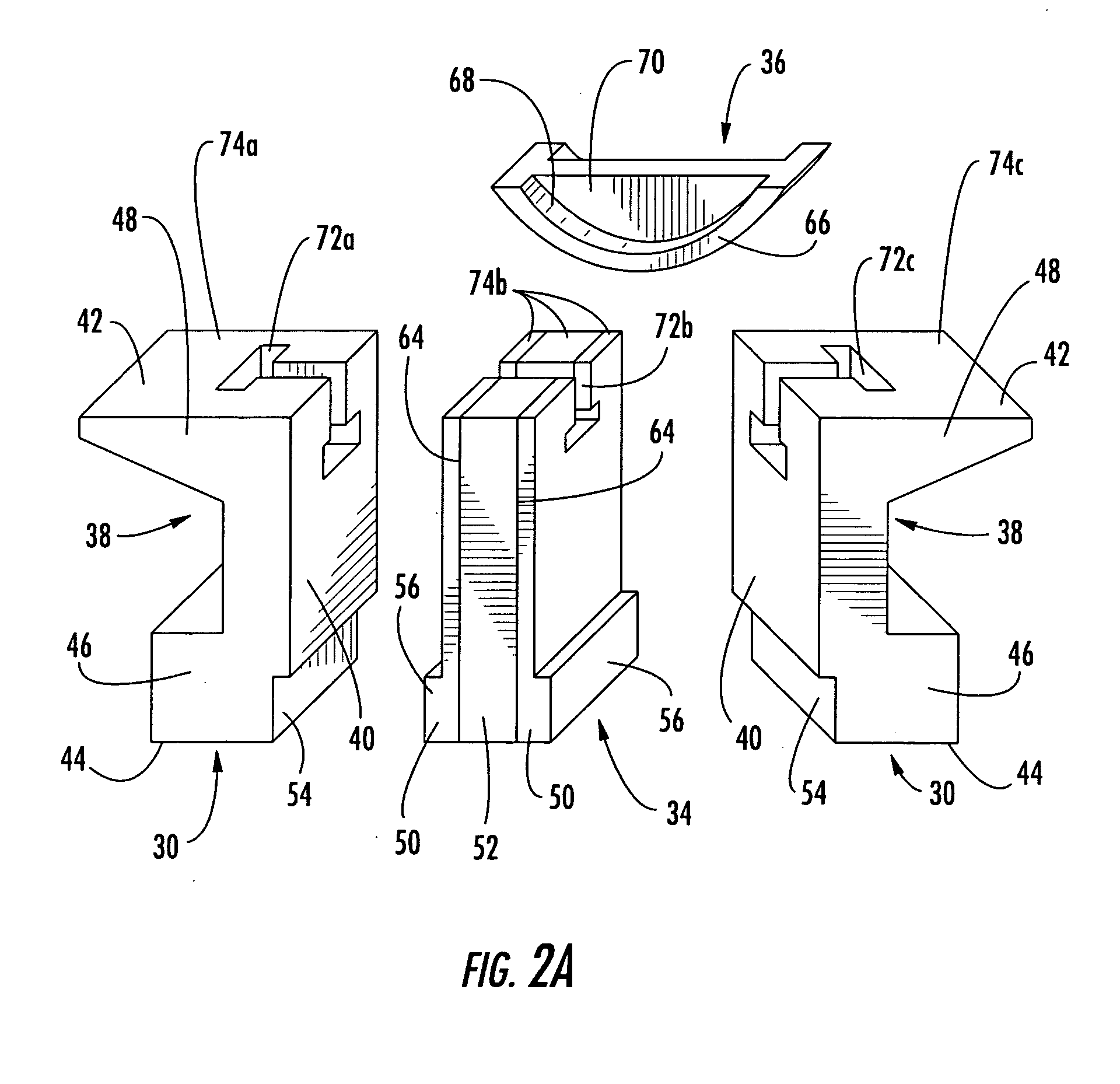
[0025] Aspects of the present invention relate to spacer assemblies for filling a void in a slotted turbine engine component. The following detailed description is directed to various embodiments of spacer assemblies according to aspects of the invention, presented in the context of slotted turbine blade or compressor discs, but the features disclosed herein can be applied to other slotted turbine engine components. The present invention is not limited to the illustrated structure or application, and the following detailed description is intended only as exemplary.

[0026] Aspects of the invention can be applied to a variety of turbine engine systems. A turbine engine can generally include a compressor section, a combustor section and a turbine section. Each of these sections can have a variety of components and configurations as would be appreciated by one skilled in the art. For example, the compressor section can include a rotor on which a plurality of discs are attached. The disc...


PUM


Abstract

Aspects according to the invention relate to a locking spacer assembly for a slotted turbine engine component. In one embodiment, aspects of the invention can be used in connection with the assembly and disassembly of a disc hosting a row of airfoils as can be found in the compressor or turbine section of a turbine engine. The spacer according to the invention is a multi-part assembly. In one embodiment, the spacer includes at least three sub-components: first and second end supports and a filler. The inner and outer faces of each of these components can have various features to facilitate engagement of the assembly and distribution of centrifugal loads in operation. These parts can be held together by a retainer, which can be received in a cutout provided in the end supports and the filler.

Description

FIELD OF THE INVENTION [0001] The invention relates in general to turbine engines and, more particularly, to spacer assemblies for filling voids in a slot of a turbine engine component. BACKGROUND OF THE INVENTION [0002] The compressor and turbine section of a turbine engine can include rotors with discs on which a plurality of blades are attached. The blades are arranged into one or more rows spaced axially along the rotor. The blades in each row are disposed about the periphery of the disc. [0003]FIG. 1 shows a common system for attaching the blades 10 to a disc 12. The disc 12, which is shown in partial section, provides a slot or groove 14 extending about the periphery of the disc 12. The slot or groove 14 can have any of a number of configurations. [0004] Each blade 10 has a root portion 17 at its base which is closely profiled to match the shape of the disc groove 14. Each blade 10 is retained by sliding the root 16 of the blade 10 into the disc groove 14. As a result of the c...

Claims


Application Information

Patent Timeline
IPC IPC(8): F01D5/30
CPCF01D5/32F01D5/303F01D5/3038
Inventor KITE, EDWIN L.POTTER, BRIANMATHENY, PAUL
Owner SIEMENS ENERGY INC
Learn More