Molecular binding event detection using separation channels

Inactive Publication Date: 2005-06-16
XEROX CORP
View PDF10 Cites 27 Cited by
  • Summary
  • Abstract
  • Description
  • Claims
  • Application Information

AI Technical Summary

Benefits of technology

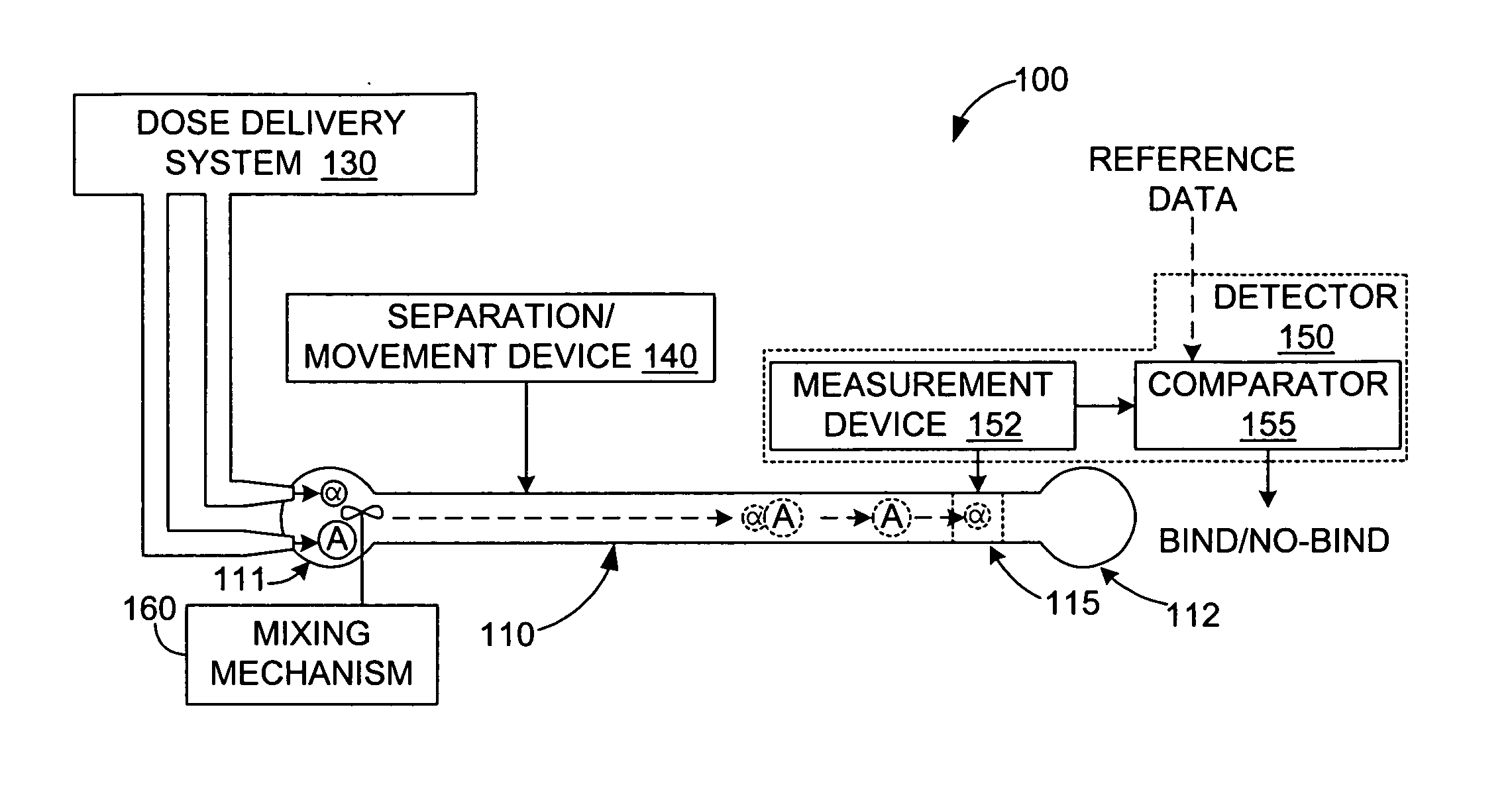
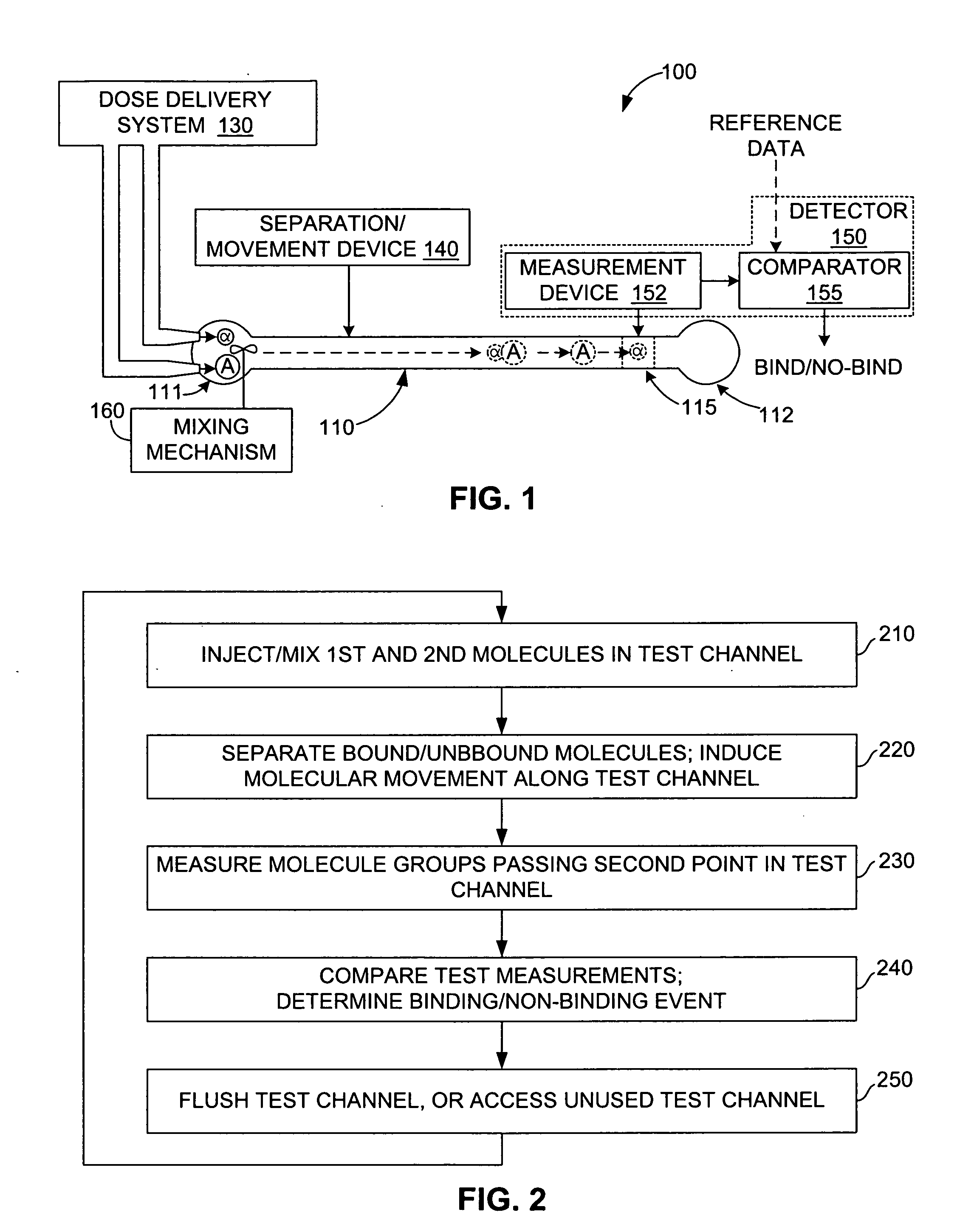
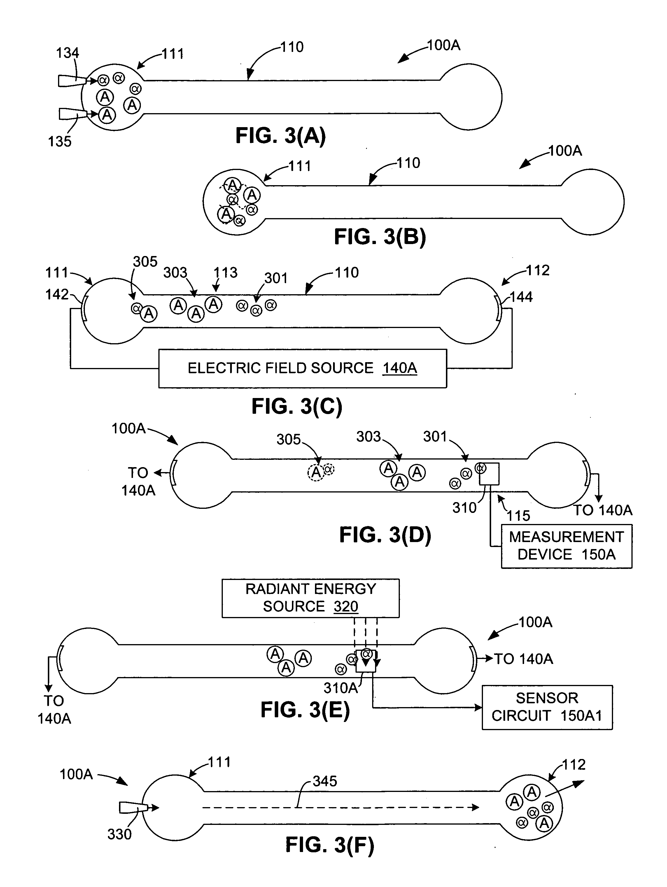
[0005] The present invention is directed to a method and apparatus for detecting binding events between two or more molecules (e.g., a ligand and a protein) that includes mixing the molecules at a first location in a test channel, separating the bound/unbound molecules (e.g., using electrophoresis) such that groups of bound and unbound molecules move along the channel at different rates, detecting and measuring the size of the bound/unbound molecule groups, and then comparing the measurement values against established reference data to determine whether a binding event has occurred. Mixing involves, for example, injecting sub-nanoliter-sized doses of a selected ligand and a selected protein into a receptor well located at a first end of the test channel, and activating a suitable mixing mechanism. Separating involves, for example, applying a suitable motive force (e.g., an electric field) that causes the bound and unbound molecules to separate into three possible groups that move along the channel at different rates: the smaller unbound ligands may, for example, form a first (fastest) group in the channel, followed by the larger unbound proteins, and then the bound ligand/protein pairs. The actual magnitudes and sign of dispersed molecular velocities depends on the particular channel structure, channel filling (e.g. particle packing, gel, empty, etc.), motive mechanism, molecular properties (e.g. charge, mass, size, state of naturation, etc.) Detection and measurement of the size of each group (i.e., an estimate of the number of molecules in each group) is performed using a stationary detector (e.g., a bolometer) that is positioned at a second location along the test channel. Finally, these measurements are then compared with reference data to determine whether a binding event has occurred, and can be used to estimate the relative strength of the binding event. For example, in one embodiment, the detection of two relatively large groups passing the detector may be interpreted as groups of unbound ligands and unbound proteins, thereby indicating a non-binding event. In contrast, two smaller groups followed by a larger group, or a single large group may be interpreted to indicate moderate to strong binding between the proteins and ligands. Accordingly, the present invention provides a generic and inexpensive method for detecting molecular binding events.
[0006] According to an embodiment of the present invention, photothermal detection is utilized to measure extremely small (e.g., sub-nanoliter) doses of the bound/unbound molecular groups moving in the test channel. In one embodiment, a radiant energy source is transmitted into the test channel at a wavelength that is absorbed by the moving molecules, but is not significantly absorbed by the channel liquid (e.g., water) in which the molecules are suspended. To further enhance optical absorption by the molecules, the radiant energy is repeatedly passed through the channel using a reflecting device (e.g., an etalon). The optically absorbed energy is converted to heat by the molecules and dissipated in the liquid. A highly sensitive thermometer (e.g., a bolometer) is positioned in the channel and utilized to generate temperature profiles indicating local heating of the channel liquid as the groups of bound and unbound molecules pass through. The temperature profiles are then analyzed (e.g., compared with reference data) to determine whether a binding event has taken place. Accordingly, the present invention facilitates binding event detection using very small (e.g., sub-nanoliter) molecule doses.
[0007] According to another embodiment, an apparatus for detecting binding events utilizes both a test (first) channel and a reference (second) channel or channels that are substantiall

Problems solved by technology

The detection of binding events between two organic molecules

Method used


Image

  • Molecular binding event detection using separation channels
  • Molecular binding event detection using separation channels
  • Molecular binding event detection using separation channels

Examples


Example

DETAILED DESCRIPTION OF THE DRAWINGS

[0027] The present invention is described below with specific reference to binding events involving a selected ligand / protein pair. The use of ligand / protein pairs is intended to be exemplary, and the methods and apparatus described herein may be used to detect binding events between other molecule types, and further may be expanded to detect binding events involving three or more molecule types. Moreover, the components and processes described herein with reference to certain specific embodiments are intended to be exemplary, and not intended to be limiting unless otherwise specified in the appended claims.

[0028]FIG. 1 is a simplified schematic diagram depicting an apparatus 100 for detecting binding events between a ligand (first molecule) a and a protein (second molecule) A according to a simplified embodiment of the present invention. Apparatus 100 generally includes a test channel 110, an optional dose delivery system 130, a molecular separ...


PUM


Abstract

Detecting binding events between first and second molecules (e.g., ligands and proteins) includes mixing at the first end of a test channel, then separating the bound/unbound molecules (e.g., using electrophoresis) by causing the molecules to move down the channel such that groups of bound/unbound molecules move along the channel at different rates. The groups are then detected, measured and compared against established reference data to determine whether a binding event has occurred. A reference channel is utilized to provide reference data and to identify unbound molecule groups. Radiant energy and a bolometer are utilized to measure the molecule groups

Description

FIELD OF THE INVENTION [0001] The present invention is related to biomedical testing systems and methods, and in particular to systems and methods for detecting binding events between two molecules. BACKGROUND OF THE INVENTION [0002] The detection of binding events between two organic molecules is an important issue in biological studies and drug discovery. There seem to be no generic (i.e., independent of the specific molecules involved in the binding process) and inexpensive methods for detecting molecular binding, much less methods for fabricating arrays that can be used to assay many thousands of possible binding pairs in parallel. [0003] Proteomics represents one branch of biological studies in which the detection of binding events is particularly important at this time. Proteomics involves the use of various techniques to analyze the structure, function, and interactions of proteins in order to, for example, identify and generate new drugs. Recent achievements in genetic resea...

Claims


Application Information

Patent Timeline
IPC IPC(8): G01N27/447G01N33/543G06F19/00G16B20/30
CPCG01N27/44726G06F19/18G01N33/54333G16B20/00G16B20/30
Inventor BIEGELSEN, DAVID A.STREET, ROBERT A.
Owner XEROX CORP
Why Eureka
Try Eureka