Device for detecting infrared radiation comprising a resistive imaging bolometer, a system comprising an array of such bolometers and a method for reading an imaging bolometer integrated into such a system

a technology of resistive imaging and bolometer, which is applied in the field of infrared imaging and pyrometry using bolometer, can solve the problems of limiting the market penetration of uncooled bolometric detectors for applications, limiting its response time, and bolometers having trouble keeping pace with such variations, and achieves high thermal resolution. the effect of performan

Active Publication Date: 2009-06-18
ULIS SAS
View PDF7 Cites 21 Cited by
  • Summary
  • Abstract
  • Description
  • Claims
  • Application Information

AI Technical Summary

Benefits of technology

[0027]According to the invention, this device comprises means of controlling the resistance of the imaging bolometer by injecting current into the bolometer. Thus, with the aid of this means of control, it is possible to set the resistance of the bolometer to a predetermined reference value at least once for every read cycle of the bolometer. The effect of this is to cancel the thermal memory effect of the bolometer each time before it is read, thus eliminating background noise and any blurring phenomenon, as well as eliminating effect of variations of stray resistances without relationship with the scene.
[0030]The invention also substantially improves the detector in terms of its offset and gain dispersion, thereby making it possible to simplify its implementation.
[0034]In one particular embodiment of the invention, the means of control is capable of fixing the resistance of the imaging bolometer to a reference resistance which depends on the temperature of the substrate above which the imaging bolometer is formed.
[0038]Note also that the forms of circuits used to temperature control the reference resistance, regardless whether they are analogue or digital, make it possible not only to maintain adequate positioning of thermalization when the operating temperature changes, they also make it possible to ensure this adequate positioning when the actual resistances of the bolometers change over time at a constant temperature. In fact, the sensitive materials incorporated in the bolometric membranes have a tendency to drift very slowly during the service life of the detector. Over time, this drift limits the relevance of initial stimuli settings even if the detector operates at a stabilised constant temperature.

Problems solved by technology

This thermal time constant is inherent in every bolometer and has a detrimental effect which limits the market penetration of uncooled bolometric detectors for applications that involve onboard vision systems or tracking moving objects for example.
The time constant τth of a bolometer is high and this limits its response time.
Thus, if the scene is prone to rapid variations in contrast, such as, for instance, the intrusion of an object that has a higher (or less high) temperature than that of the background of the scene (this is referred to as a “hot” or “cold” object), the bolometer has trouble keeping pace with such variations.
Movement of a hot (or cold) object in the scene will therefore result in a blurring or smearing in the image formed.
This effect is similarly detrimental when dealing with a fixed scene in which, locally, there are rapid temperature fluctuations.
The bolometer has trouble responding to variations that are faster than its time constant and therefore finds it difficult to reproduce the scene faithfully.
Also, the dispersed resistance values of the various elementary conductors results in dispersed current flow through them during readout.
However, it is difficult to reduce the heat capacity Cth of a bolometer insofar as its heat capacity depends on the quantity of material used in order to fabricate the bolometer.
Reducing the mass of the bolometer has the direct consequence of increasing the electrical noise of the bolometer because electrical noise power is related to the volume of the bolometer, at least when thermometric materials having a non-negligible low-frequency noise level are used.
Moreover, geometric stability of the sensitive structures can no longer be ensured if there is less than an adequate quantity of structural material and this quantity cannot simply be reduced at will.
What is more, reducing the thermal resistance Rth is not a satisfactory solution.

Method used


Image

  • Device for detecting infrared radiation comprising a resistive imaging bolometer, a system comprising an array of such bolometers and a method for reading an imaging bolometer integrated into such a system
  • Device for detecting infrared radiation comprising a resistive imaging bolometer, a system comprising an array of such bolometers and a method for reading an imaging bolometer integrated into such a system
  • Device for detecting infrared radiation comprising a resistive imaging bolometer, a system comprising an array of such bolometers and a method for reading an imaging bolometer integrated into such a system

Examples


Embodiment Construction

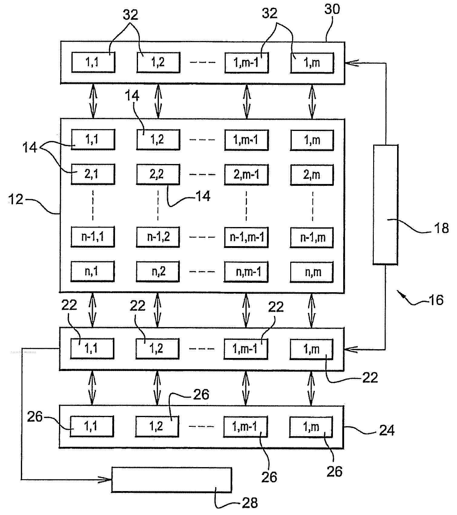
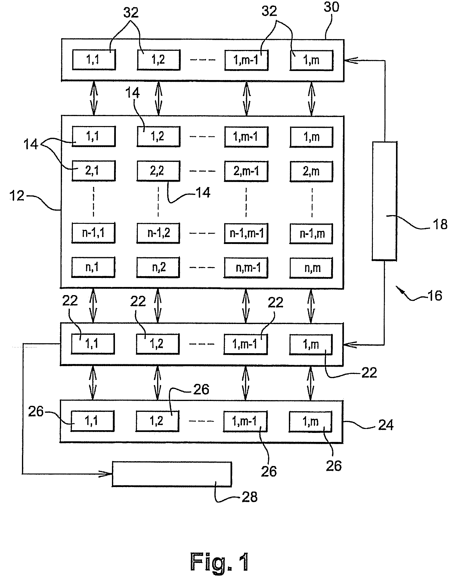
[0059]FIG. 1 schematically shows a bolometric detector which comprises:[0060]A two-dimensional imaging array 12 comprising n rows and m columns of resistive imaging bolometers 102, where n and m are integers equal to or greater than 1. The imaging array 12 is arranged in the focal plane of optics that are transparent to infrared radiation (not shown);[0061]A readout circuit 16 implemented in a substrate underneath the surface of the imaging array 12. Readout circuit 16 comprises a row-by-row addressing circuit 18 and, for each column of imaging array 12, a measuring circuit 22 capable of being connected to every imaging bolometer in their column by electrical means;[0062]An array of compensation bolometers 24 comprising one or more compensation circuits 26 located opposite every column of imaging array 12, but positioned off the imaging array. Array 24 comprises, for example, for every column of imaging array 12, a compensation circuit 26 capable of being connected to every imaging ...


PUM


Abstract

A device for detecting infrared radiation comprising a resistive imaging bolometer intended to be electrically connected to a circuit for measuring a resistance of the bolometer. It comprises means of controlling the resistance of the imaging bolometer by injecting current into the bolometer.

Description

FIELD OF THE INVENTION[0001]The present invention relates to the field of infrared imaging and pyrometry using bolometers.[0002]More particularly, the present invention relates to a device for detecting infrared radiation comprising a resistive imaging bolometer. It also relates to a system comprising an array of such devices as well as a method for reading an imaging bolometer integrated into such a system.DESCRIPTION OF THE PRIOR ART[0003]In the field of infrared detectors, the use of devices configured in the form of an array and capable of operating at ambient temperature, i.e. not requiring cooling to extremely low temperatures, are known—in contrast to detecting devices referred to as “quantum detectors” which can only operate at extremely low temperature, typically that of liquid nitrogen.[0004]These uncooled detectors traditionally use the variation in a physical unit of an appropriate material as a function of temperature at around 300 K. In the case of bolometric detectors...

Claims


Application Information

Patent Timeline
Patent Type & Authority Applications(United States)
IPC IPC(8): G01J5/00G01J5/03
CPCG01J5/24H04N5/33H04N25/673
Inventor DUPONT, BENOITVILAIN, MICHEL
Owner ULIS SAS
Why Eureka
Try Eureka