Ultra sensitive silicon sensor millimeter wave passive imager

a passive imager and ultra-sensitive technology, applied in the field of bolometer type sensors, can solve the problems of less performance than quantum detectors, less sensitive bolometers, and reduced slow speed limitation, so as to maximize the sensitivity of the absorber element and reduce the thermal conductivity

Active Publication Date: 2005-04-28
NORTHROP GRUMMAN SYST CORP
View PDF3 Cites 20 Cited by
  • Summary
  • Abstract
  • Description
  • Claims
  • Application Information

AI Technical Summary

Benefits of technology

[0012] These and other objects are achieved by a method and apparatus including a two tier ultra sensitive silicon sensor comprising: a heat bath for the sensor; an antenna element for receiving thermal radiation; an absorber element coupled to the antenna element for detecting thermal radiation; and an intermediate stage for thermally isolating the absorber element from the heat bath. The antenna is directly mounted on the heat bath approximately coplanar with the absorber element and the intermediate stage. Support elements mutually separate the absorber element, the intermediate stage, and the heat bath. The intermediate stage includes a electro-thermal feedback circuit including a transistor ampifier for reducing the thermal conductivity between the absorber element and the heat bath by causing the temperature of the intermediate stage to converge to the temperature of the absorber element when detecting thermal radiation, effectively causing the thermal conductance of the support elements to attain a minimum conductance value and thereby maximize the sensitivity of the absorber element to the thermal radiation limit. Temperature sensing is achieved by using the forward voltage of a diode in place of the heretofore used thermal EMF voltage. A plurality of these sensors are intended to fuse in an imaging array.

Problems solved by technology

Such performance is less than that of quantum detectors, however, for many applications it is adequate and cost effective.
However, with staring focal plane arrays, the slow speed limitation is alleviated, since the pixel integration times correspond to the frame rate, and is much longer than line times in scanning systems.
Thus the main obstacle to making bolometers more sensitive are practical limitations in thermally isolating each pixel element.

Method used


Image

  • Ultra sensitive silicon sensor millimeter wave passive imager
  • Ultra sensitive silicon sensor millimeter wave passive imager
  • Ultra sensitive silicon sensor millimeter wave passive imager

Examples


Embodiment Construction

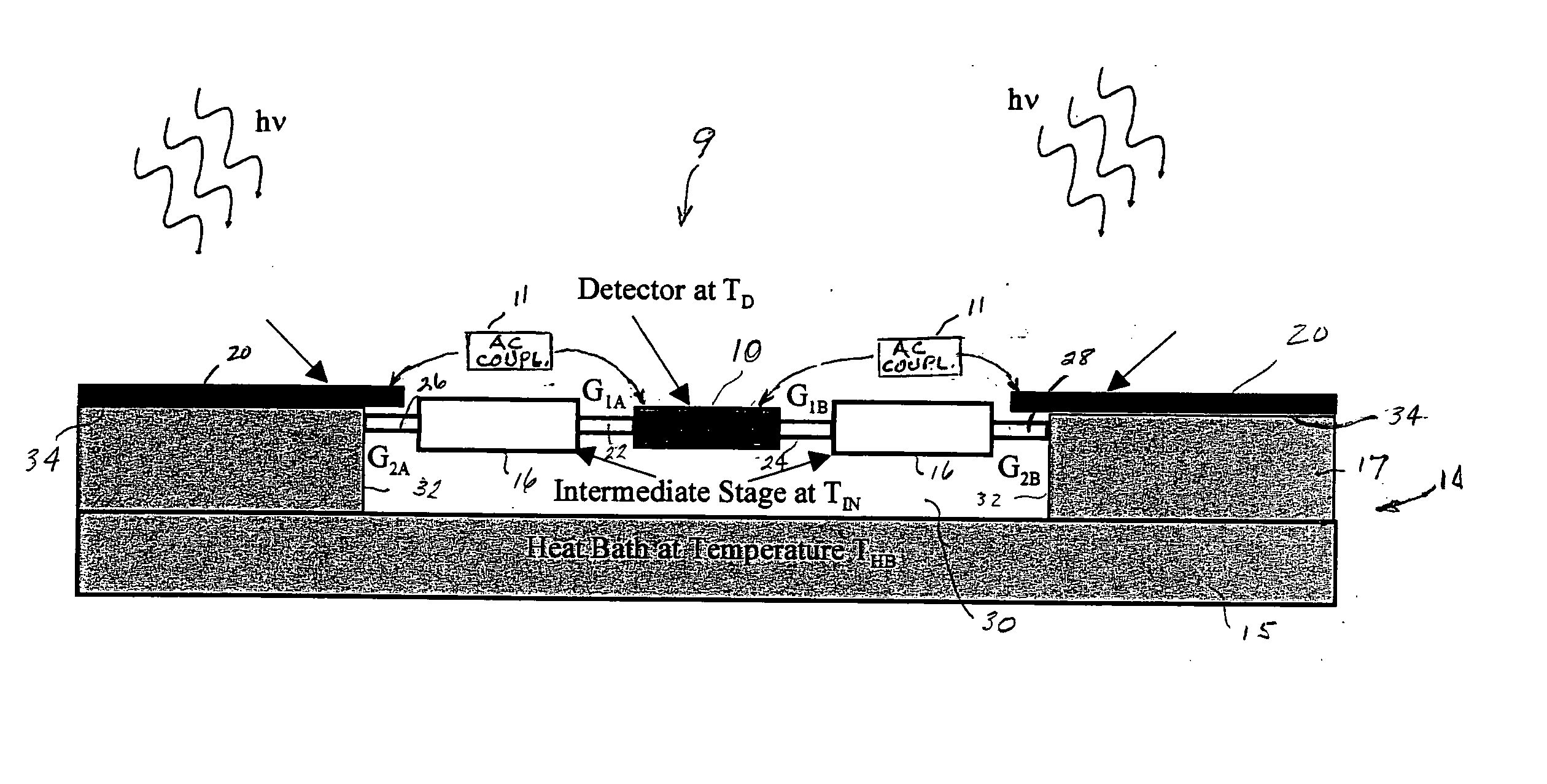
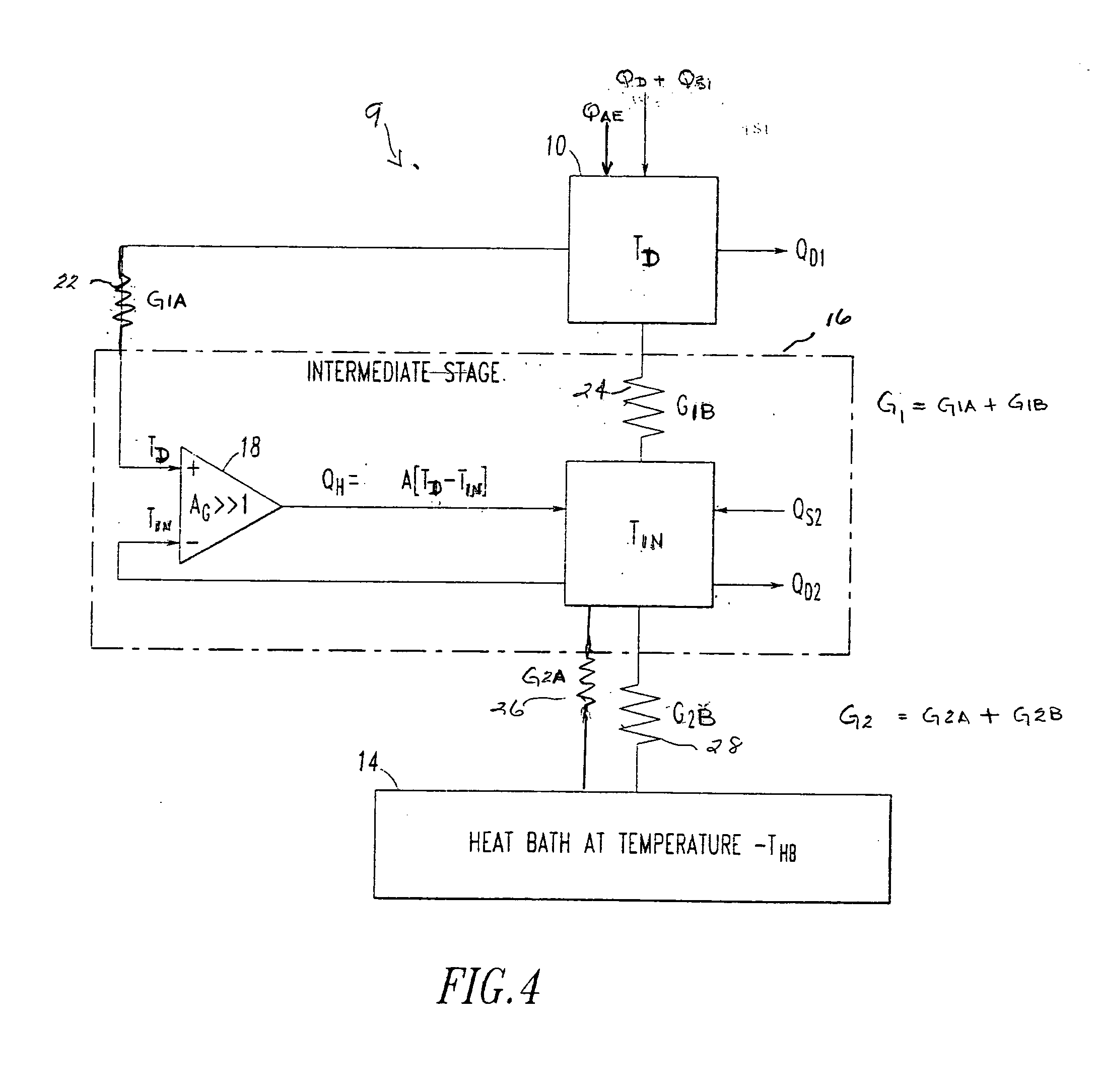
[0026] With improved thermal isolation, performance of bolometers will directly improve and thereby open a wider range of applications, such as the application of bolometers as passive millimeter (MM) wave staring imagers. Accordingly, means are now presented for greatly improving the thermal isolation in bolometers. This requires within each bolometer pixel, the zeroing of the thermal conductance of an MM pixel between the detector and its mechanical support and readout structures. Achieving improved thermal isolation to the radiation limit will lead to at least a ten-fold improvement in performance. Zeroing the thermal conductance associated with the mechanical support and readout structures is achieved in the subject invention by introducing an improved intermediate stage and electrical-thermal feedback over that shown and described in U.S. Pat. No. 6,489,615 which vary the temperature of the intermediate stage to track changes in the detector's temperature thereby zeroing the ne...


PUM


Abstract

Electro-thermal feedback is utilized for zeroing the thermal conductance between a bolometer type detector element of a pixel in a thermal radiation sensor assembly and the environments through its mechanical support structure and electrical interconnects, thereby limiting the thermal conductance primarily through photon radiation. Zeroing of the thermal conductance associated with the mechanical support and electrical readout interconnect structures is achieved by electro-thermal feedback that adjust the temperature of an intermediate stage by the heating effect of a bipolar transistor amplifier circuit so that the temperature across the mechanical support and electrical interconnects structures are zeroed thereby greatly improving the thermal isolation, the responsivity and sensitivity of the electromagnetic radiation sensor.

Description

BACKGROUND OF THE INVENTION [0001] 1. Field of the Invention [0002] This invention relates generally to bolometer type sensors for detecting thermal radiation and more particularly to ultra sensitive silicon bolometer type sensors usable for passive or active imaging at millimeter (MM) wavelengths. [0003] 2. Description of Related Art [0004] Infrared (IR) bolometers are used and proposed for use in many new applications. The principal application is construction of thermal cameras. Interest in bolometers stems from the fact that their performance has significantly improved, they're sensitive at much longer wavelengths, and offer higher operating temperatures. Specifically, IR cameras, with large bolometer arrays have achieved a sensitivity, a Noise Equivalent Temperature resolution (NEΔT) better than ≈0.1K. Such performance is less than that of quantum detectors, however, for many applications it is adequate and cost effective. Improved bolometer performance is achieved primarily th...

Claims


Application Information

Patent Timeline
Patent Type & Authority Applications(United States)
IPC IPC(8): G01J5/20
CPCG01J5/20
Inventor BLUZER, NATHAN
Owner NORTHROP GRUMMAN SYST CORP
Why Eureka
Try Eureka