Large temperature coefficient of resistance material

a resistance material and large temperature coefficient technology, applied in the field of resistor materials, can solve the problems of insignificant constancy over a wide temperature range, temperature change, and insignificant increas

Inactive Publication Date: 2002-01-08
CORNING APPLIED TECH
View PDF17 Cites 20 Cited by
  • Summary
  • Abstract
  • Description
  • Claims
  • Application Information

AI Technical Summary

Problems solved by technology

However, these always exhibit a change in resistance with temperature.
In a typical application, this increase is minute and constancy over a wide temperature range is unimportant.
The large thermal barrier generally results in large resistivities which have the potential for non-ohmic contacts, and large 1/f noise levels.
When making a magnetic field sensor, a high TCR i

Method used


Image

  • Large temperature coefficient of resistance material
  • Large temperature coefficient of resistance material
  • Large temperature coefficient of resistance material

Examples


example 2

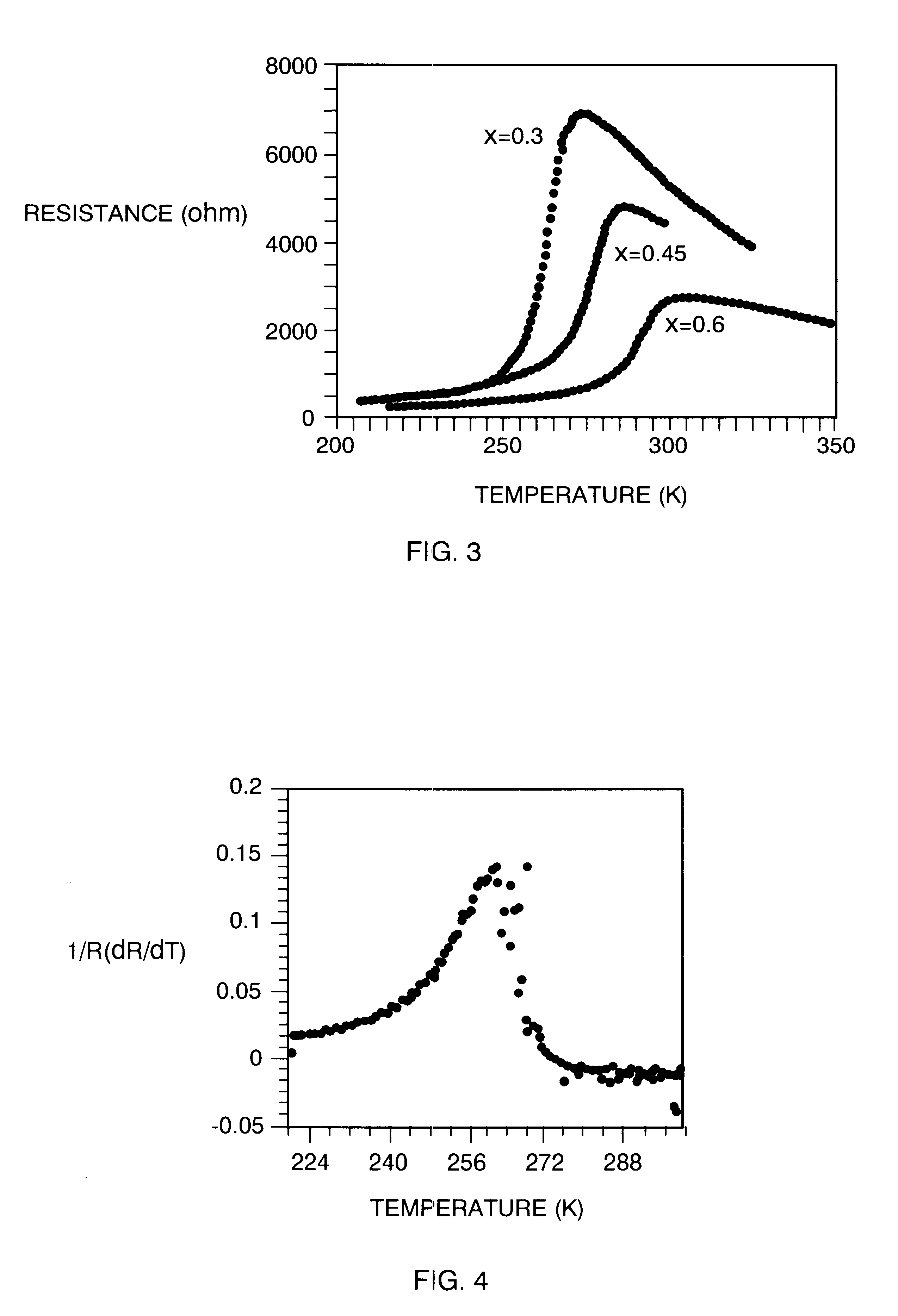
with nominal composition (La.sub.0.7 Pb.sub.0.3)MnO.sub.3 and (La.sub.0.7 Ca.sub.0.3)MnO.sub.3 were deposited on (100) LaAlO.sub.3 substrates with an MOCVD system under the deposition condition listed in Example 1. The resulting layers were epitaxial with the substrates. The resistivity of both layers as a function of temperature was measured by a conventional four-probe method. The (La.sub.0.7 Pb.sub.0.3)MnO.sub.3 layer showed a broad magnetic transition with a peak resistance temperature of about 350.degree. K. The TCR of the layer peaked at 295.degree. K, but was a relatively low 1.7% / .degree. C. In contrast, the (La.sub.0.7 Ca.sub.0.3)MnO.sub.3 layer showed a sharp magnetic transition with a peak temperature of about 260.degree. K. The TCR of the layer was a high 15% / .degree. C. at 240.degree. K.

example 3

tion of calcium and lead in substitution for lanthanum showed a trade-off between transition temperature and the TCR characteristic. FIG. 5 shows the resistance as a function of temperature for (La.sub.0.6 Ca.sub.0.3 Pb.sub.0.1)MnO.sub.3 and (La.sub.0.6 Ca.sub.0.2 Pb.sub.0.2)MnO3 layers deposited on (100) LaAlO.sub.3 substrates by MOCVD under the deposition conditions as listed in Example 1. The film with a composition (La.sub.0.6 Ca.sub.0.3 Pb.sub.0.1)MnO.sub.3 had a TCR=12% / .degree. C. at 263.degree. K, 10% / .degree. C. at 273.degree. K, and 7% / .degree. C. at 278.degree. K while the film with a composition (La.sub.0.6 Ca.sub.0.2 Pb.sub.0.2)MnO.sub.3 had a TCR=5.6% / .degree. C. at 263.degree. K, 6.4% / .degree. C. at 273.degree. K and 6% / .degree. C. at 278.degree. K.

example 4

ystal substrates of (100) yttrium stabilized zirconia (YSZ) were provided. (La.sub.0.6 Ca.sub.0.3 Pb.sub.0.1)MnO.sub.3 films were deposited on bare YSZ, CeO.sub.2 buffered YSZ, Yba.sub.2 Cu3O.sub.7 (YBCO) deposited on CeO.sub.2 buffered YSZ, and YBCO buffered YSZ substrates under the same deposition conditions listed in Example 1. Both the YBCO and CeO.sub.2 layers were also deposited in the same CVD chamber and under the same conditions listed in Example 1 used for deposition of the (La.sub.0.6 Ca.sub.0.3 Pb.sub.0.1)MnO.sub.3 films. 2% cobalt was doped into the YBCO layer to increase its resistivity. FIGS. 6A and 6B (wherein (La.sub.0.6 Ca.sub.0.3 Pb.sub.0.1)MnO.sub.3 is designated by LPCMO) show that the film directly deposited on the YSZ substrate was (110) oriented and had a very broad magnetic phase transition at 223.degree. K and thus a low TCR characteristic. However, the film deposited on the CeO.sub.2 buffer layer on YSZ has a mixed orientation of (100) and (110) and a much...


PUM


Abstract

Oxide thin films having a perovskite-like structure and undergoing a ferromagnetic phase transition with large temperature coefficients of resistance (TCRs) are disclosed. These can be useful materials for making thermistors, bolometers, infrared detectors and the like. These can be fabricated with a number of methods, preferably including metal oxide chemical vapor deposition, laser ablation and sputtering. In one embodiment, the oxides are based on a LaMnO3 with substitutions of Ca, Sr, Ba, Mn, and Pb for some of the La. The amounts can be varied to maximize the TCR or shift the temperature at which the maximum occurs. Methods of making such thin films are disclosed. In one embodiment, the high sensitivity films can be used in an array of micro-bolometers in an infrared camera.

Description

1. Technical FieldThe invention relates to resistor materials that are particularly sensitive to changes in temperature and find use in thermistors, bolometers, infrared detectors and the like.2. Background of the InventionIn many applications, resistors are preferably made from materials whose resistivity is constant with temperature. However, these always exhibit a change in resistance with temperature. Quite often, this change is sensibly linear and is characterized by a sensibly constant temperature coefficient of resistance (TCR) which is numerically equal to the fractional change in resistance, dR, with change in temperature, dT, and given by (1 / R) (dR / dT). (TCR is a more useful characteristic than dR / dT because the absolute resistance can be changed by changing the geometry of the resistor.) For resistor applications, some alloys have TCRs in the parts per million per .degree. C. range. However, other materials have much higher TCRs and can be used as temperature sensors, com...

Claims


Application Information

Patent Timeline
IPC IPC(8): C30B25/18C30B25/02C30B23/02G01J5/20H01L31/0304H01L31/101H01L37/00
CPCC30B23/02C30B25/02C30B25/18G01J5/20H01L31/03046H01L31/101C30B29/225H01L37/00C30B29/22Y02E10/544H10N15/00
Inventor LI, YI-QUNZHAO, JING
Owner CORNING APPLIED TECH
Why Eureka
Try Eureka