Configurable connectorized I/O system

a connectorized i/o system and configuration technology, applied in the direction of electrical programme control, programme control, coupling device connection, etc., can solve the problems of inconvenient arrangement of the cable from the input or output module to the plc, the inability to generally connect directly to the sensor or actuator, and the inability to facilitate the connection of the cable. , to achieve the effect of reducing the time required, eliminating or minimizing the need for custom cable harnesses

Inactive Publication Date: 2005-06-16
BERKELEY PROCESS CONTROL
View PDF13 Cites 17 Cited by
  • Summary
  • Abstract
  • Description
  • Claims
  • Application Information

AI Technical Summary

Benefits of technology

[0012] It is therefore an object of the present invention to provide a method and apparatus wherein customized connections can be made using standard cables.
[0013] It is another object of the present invention to provide a method and apparatus that reduces the cable complexity involved in making interconnections in control systems.
[0014] It is a further object of the present invention to provide a method and apparatus for reducing the number of custom designed cables and individual wire connections in a system.

Problems solved by technology

A disadvantage of the method illustrated in FIG. 1 is that the terminals 26, 28 on the input or output modules of the PLC 16 are not necessarily conveniently arranged for facilitating easy connection of a load, such as a light bulb or switch.
The custom wiring design and implementation illustrated in FIG. 1 significantly adds to the cost and size of the system.
Unfortunately, the cable from the input or output module cannot generally connect directly to the sensor or actuator because the connectors 38 and 40 on the PLC 36 are rarely configured to accept a sensor signal or provide the actuator power.
Therefore, even when connectorized cables are employed, the prior art still requires making connections through use of individual wire connections such as terminal blocks.
Making a direct connection between a PLC and a sensor or actuator without individual wire connections is problematical.
In this case, the connections are complicated by the fact that the PLC output module contains only outputs and the PLC input module contains only inputs, whereas the mass flow controller connector contains signals that represent both inputs and outputs.
The difficulty of designing, fabricating and installing complex wire harnesses is so great that the predominant method of connecting PLC's to sensors and actuators is via individual wire connections and terminal blocks.

Method used


Image

  • Configurable connectorized I/O system
  • Configurable connectorized I/O system
  • Configurable connectorized I/O system

Examples


Embodiment Construction

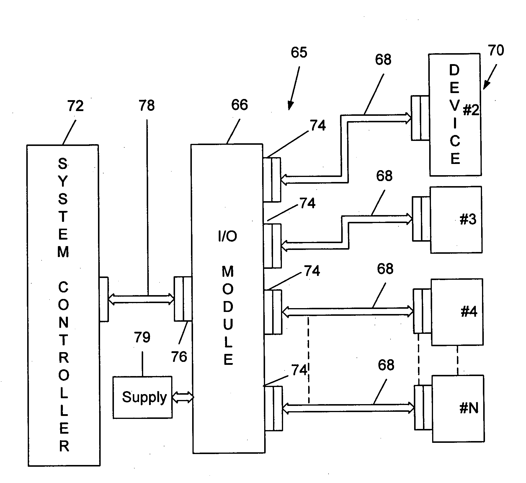
[0036] Referring now to FIG. 5 of the drawing, a block diagram is presented for illustration of the method and apparatus of a preferred embodiment of the present invention. The apparatus of the present invention includes a configurable input / output system 65 including an input / output module 66 and one or more cables 68. All of the cables 68 are preferably identical, but the present invention also includes variations in the cables 68. Each cable 68 includes one or more conductors. The I / O module 66 according to the present invention includes a microprocessor that is programmable for enabling a particular transmission of a signal between the module 66 and devices 70, and between the module 66 and a system controller 72. The module 66 also preferably includes one or more standard connectors 74 for connection to the standard cables 68. A connector 76 provides connection to a network (preferably Ethernet) 78 for communication between the module 66 and the system controller 72. The module...


PUM


Abstract

A system for making interconnections between an input / output module and a first device and a second device wherein the system uses standard cables and connectors. The input / output module includes a standard first connector for making connection with a standard first transmission line cable for conveying signals between the module and the first device, and at least one second connector, with such second connector connecting to a first end of a second standard cable. A second end of the second standard cable includes a standard cable connector for making connection to a corresponding connector of the second device. The input / output module is configured to contain programmable logic for making the required connections between the module and the first and second devices.

Description

[0001] This application is a continuation-in-part of U.S. patent application Ser. No. 10 / 071,870 filed Feb. 8, 2002, which claims the benefit of U.S. Provisional Application Ser. No. 60 / 269,129 filed Feb. 14, 2001.BACKGROUND OF THE INVENTION [0002] 1. Field of the Invention [0003] The present invention relates generally to cabling and cabling systems, and more particularly to a universal cabling system wherein the requirement for specific wire interconnections between first and second devices is accomplished through use of a programmable I / O module for making connection to the first device, and directing connections from the first device to selected wires of a cable for connection to the second device. [0004] 2. Description of the Prior Art [0005] Complex electrical / electronic systems often require custom cable configurations. Cables are usually special configurations for a particular application. Even in relatively simple systems such as home audio and small computer systems, a num...

Claims


Application Information

Patent Timeline
Patent Type & Authority Applications(United States)
IPC IPC(8): G05B19/05G06F1/18G06F3/00H01R29/00
CPCG05B19/054G05B2219/1105H01R2201/06G05B2219/1144H01R29/00G05B2219/1138
Inventor SAGUES, PAULPEUARCH, JOHN T.WOODS, LESLIE H.
Owner BERKELEY PROCESS CONTROL
Why Eureka
Try Eureka