
Method for optimizing handover between communication networks

a communication network and handover technology, applied in the field of optimizing handover between communication networks, can solve problems such as inability to solve particular problems, disruption of ip sessions, and small overlap between signals from wlan and umts networks

Inactive Publication Date: 2005-06-16
NOKIA CORP
View PDF7 Cites 235 Cited by
  • Summary
  • Abstract
  • Description
  • Claims
  • Application Information

AI Technical Summary

Benefits of technology

[0019] According to another embodiment, there is provided a method for ensuring continuity of a communication session when a user equipment hands over from a first communication network to a second cellular communication network. Attachment of the user equipment to the second network is maintained after the user equipment moves away from the coverage area of the second network for a predetermined time in order to allow the user equipment to return to the second network without having to repeat an authentication procedure and a packet data session establishment procedure before handing over to the second network.

Problems solved by technology

However, there is no attempt to solve the particular problem of how network layer (L3) IP bearers are established in conjunction with link layer (L2) authentication.
The resulting delay in handover time means that a security association has to exist between the two networks.
If the MN has to perform all the protocols described earlier, the time involved will cause a disruption in the IP session.
Furthermore, in certain situations, depending on the local environment, the region of overlap between the signals from the WLAN and UMTS networks may not be very large.
In such a scenario, it has been found that, when the MN moves from a WLAN network to a cellular network, the WLAN signal may fade very fast and, as a result, the time frame for carrying out the handover is very small.

Method used


Image

  • Method for optimizing handover between communication networks
  • Method for optimizing handover between communication networks
  • Method for optimizing handover between communication networks

Examples


first embodiment

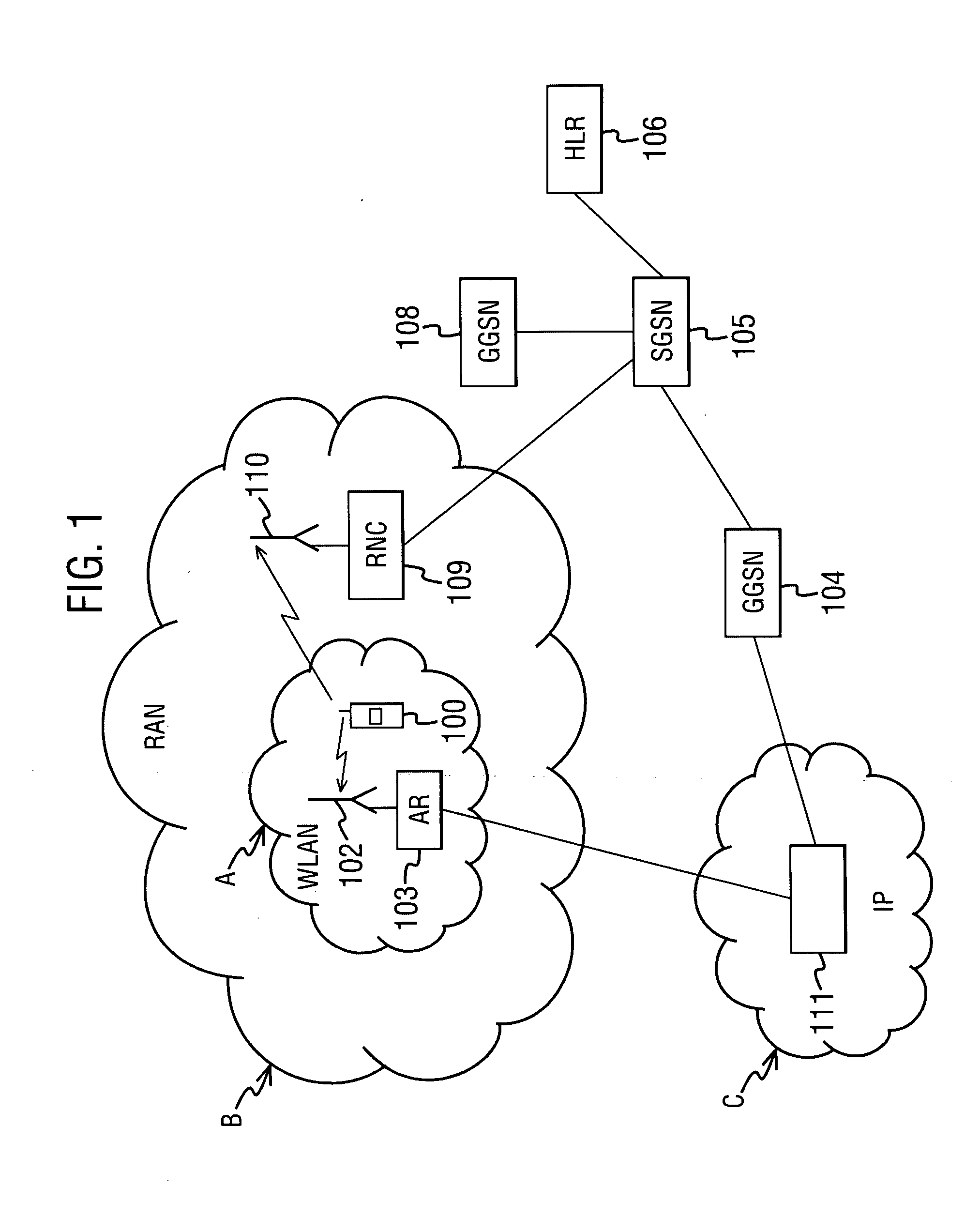
[0030]FIG. 1 illustrates a simplified presentation of the invention for handover between a WLAN network A and a GPRS network B.

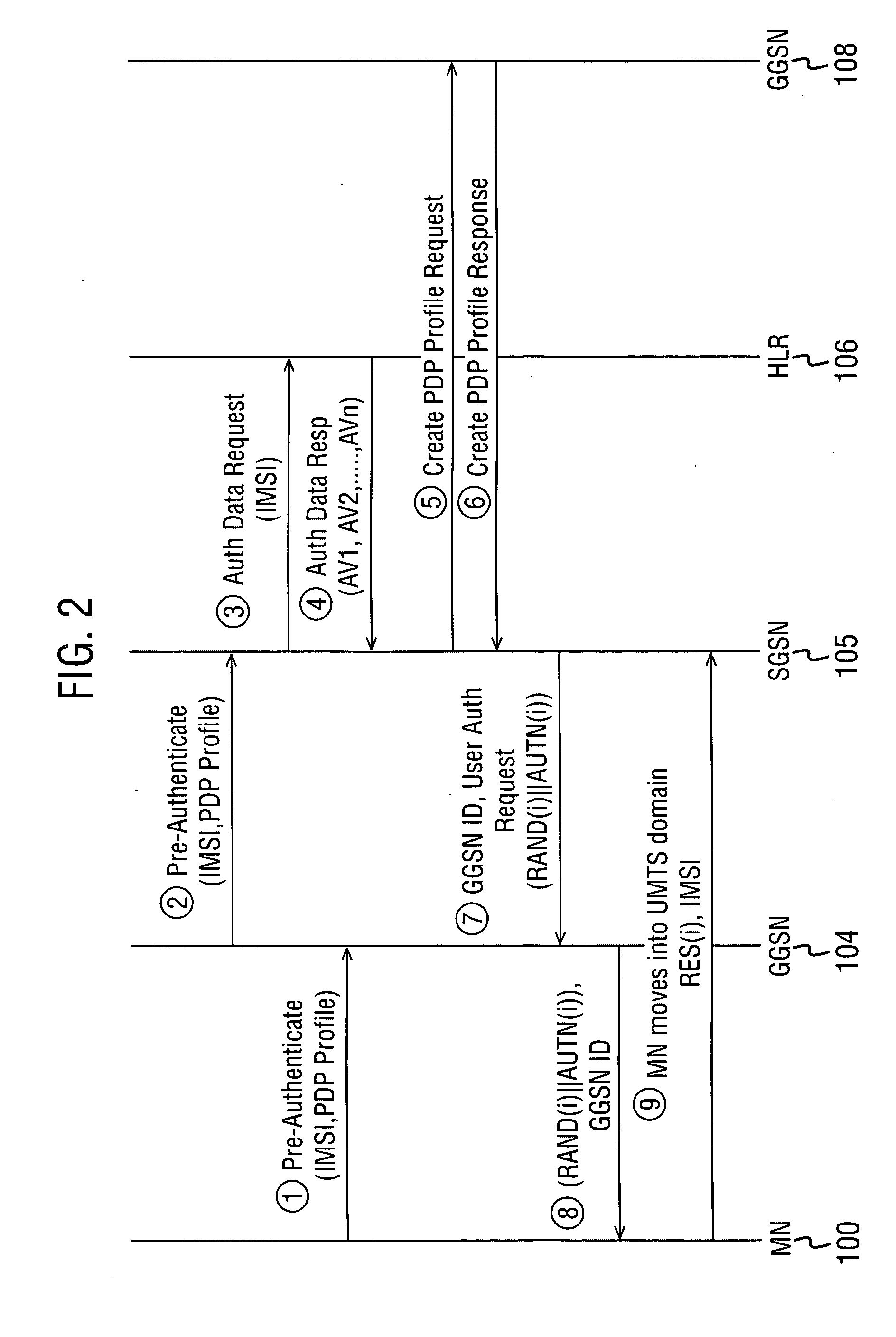
[0031] In this example, the mobile node (MN) 100 is engaged in an IP communication session between the WLAN network A and the IP network C. The IP communication session is provided by, for example, a service provider 111. The MN 100 wirelessly receives and transmits signals from and to base station 102. There is an access router (AR) 103 for routing the signals from the base station 102 to the IP network C. If the MN now moves towards the GPRS network B and the IP communication session is to continue, the invention proposes that handover is accomplished while the MN 100 is still attached to the WLAN network A. Although FIG. 1 depicts the WLAN network A as completely within the GPRS network B, in an alternative embodiment, there may simply be an overlap between the two coverage areas. The GPRS network B may include a gateway GPRS support node (GGSN) 104, a se...

second embodiment

[0050]FIGS. 3 and 4 depict the invention. In this situation, the MN will be moving into the PS (packet switched) core network rather than being supposed to be attached to the PS core network (as in FIGS. 1 and 2).

[0051] In FIG. 3, a simplified presentation of the second embodiment of the invention is shown for handover between a WLAN network A as a GPRS network B. This FIG. 3 is substantially the same as FIG. 1 except that there is only a single GGSN 104 which is able to act as the AR 103 for the WLAN network A and can host the PDP contexts of the MN 100.

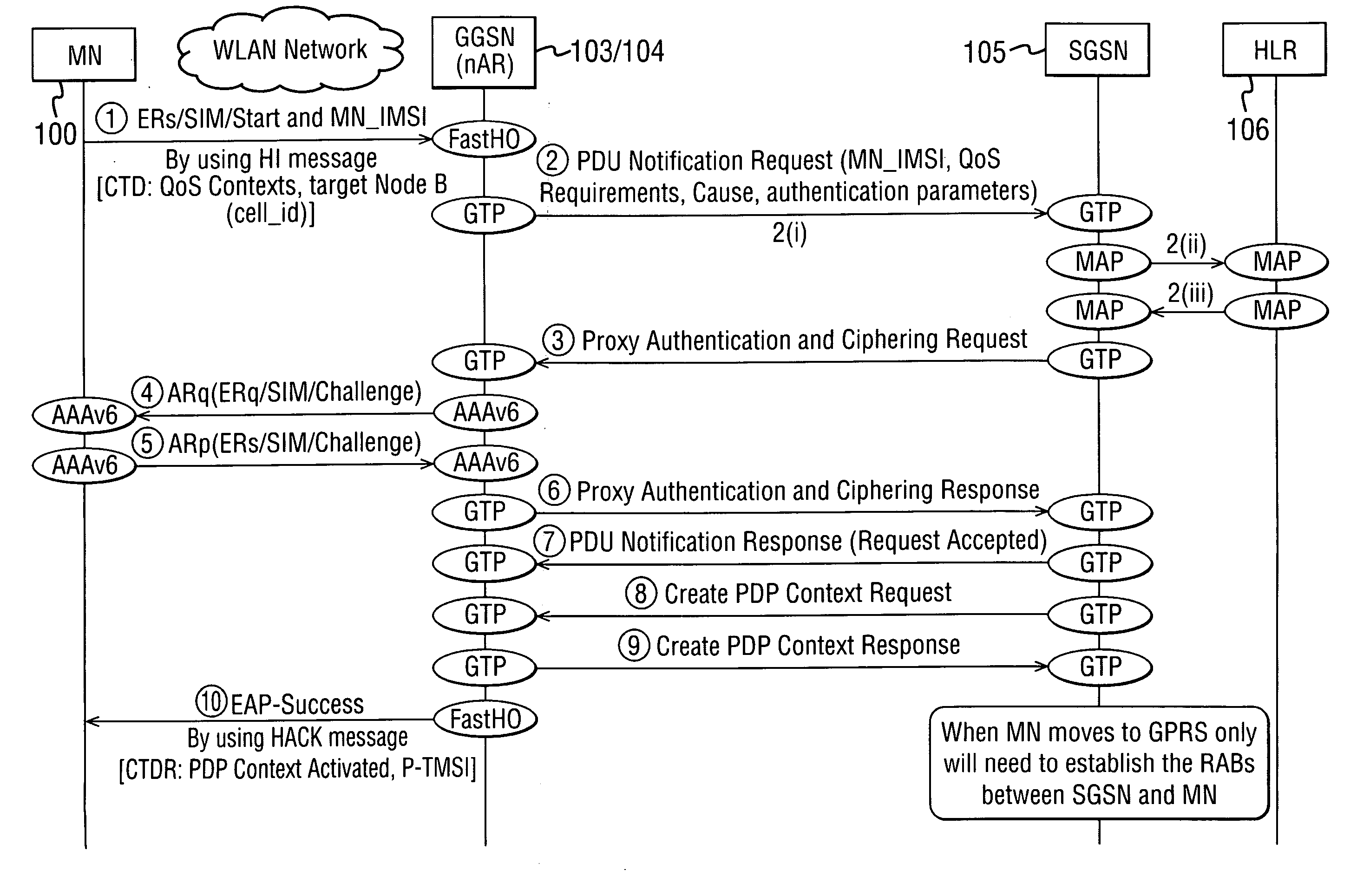
[0052] In FIG. 4, the SGSN 105 starts the authentication of the MN 100 by first obtaining the authentication parameters from the HLR 106 and then sending a Proxy Authentication and Ciphering Request message to the GGSN via the WLAN network. In FIGS. 3 and 4 the GGSN 104 acts as an AR 103 in the GPRS network B from the point of view of the MN and is capable of receiving a handover trigger indication from the WLAN network A. As menti...

third embodiment

[0091] According to the invention the MN remains attached to the GPRS network, i.e. the PDP contexts are maintained when the MN moves from the GPRS network to any other access network. Consequently, when the MN moves back to the GPRS network for a second time and subsequent times, it will not have to waste time performing attach, authentication and PDP context procedures so that the handover delay time can be reduced considerably.

[0092] The main disadvantage in maintaining the PDP contexts is that the PDP contexts may be considered to be invalid. This may occur if the ongoing applications running on the MN are completely different than those which the PDP contexts were originally activated for, i.e. the MN has moved from the GPRS network to another access network and has started to use different applications having other requirements before returning to the GPRS network. This may imply either a modification in the QoS requirements for the maintained PDP contexts or more drastically,...


PUM


Abstract

A method for ensuring continuity of a communication session when a user equipment hands over from a first communication network to a second cellular communication network is provided. The method, in one embodiment, includes the steps of performing an authentication procedure for a packet data session with the second network while still being attached to the first network and simultaneously performing a packet data session establishment procedure with the second network while still being attached to the first network.

Description

BACKGROUND OF THE INVENTION [0001] 1. Field of the Invention [0002] The invention is concerned with the optimization of the handover process when a user equipment (UE), for example, a mobile node (MN), requires a seamless transfer during movement between, for example, the coverage area of a wireless local area network (WLAN) and the coverage area of a cellular communication network. [0003] 2. Description of the Related Art [0004] Communication systems that provide users thereof with wireless communication are known. A typical example of such a system is a cellular or mobile communications system. The cellular communication system is a communication system that is based on the use of radio access entities and / or wireless service areas. The access entities are often referred to as cells. A characteristic feature of the cellular systems is that they provide mobility for the users of the communication system. Hence, they are often referred to as mobile communication systems. Another typ...

Claims


Application Information

Patent Timeline
Patent Type & Authority Applications(United States)
IPC IPC(8): H04L12/28H04L12/56H04L29/06H04W12/06H04W36/14H04W84/12
CPCH04L63/08H04W84/12H04W36/0016H04W12/06H04W12/062H04W12/069
Inventor GRECH, SANDROSERNA, PEDROKRISHNAMURTHI, GOVINDARAJANCHASKAR, HEMANT M.TROSSEN, DIRKALARCON, LEOPOLDO
Owner NOKIA CORP
Learn More